


DXP DVI Pro and DXP HDMI Series • Setup 5
Setup
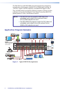
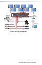
This section describes the rear panels of the DXP switchers and
provides instructions for cabling. It covers the following topics:
• Setup Procedure
• Rear Panels and Connections
• Front Panel Config Port
Setup Procedure
Follow these steps to set up and start operating the DXP switcher. See
the "Operation" section for additional configuration procedures you
may want to perform to set up the switcher.
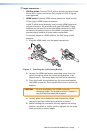
1. Turn off power to the input and output devices and disconnect
their power cords.
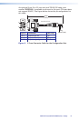
2. Connect DVI or HDMI input devices to the rear panel input
connectors (see "
b
Input connectors" on page 7).
3. Connect DVI or HDMI output devices to the rear panel output
connectors (see "
c
Output connectors" on page 8).
4. Change any required button labels (optional) (see "Replacing
Button Labels" in the "Reference Information" section of the
DXP DVI Pro and DXP HDMI Series User Guide).
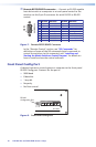
5. If desired, connect a computer or control system to the Remote
RS-232/RS-422 port or to the front panel Config RS-232 port (see
"
g
Remote RS232/RS422 connector" on page 10).
6. If desired, connect a network WAN or LAN hub, a control
system, or a computer to the rear panel Ethernet RJ-45 port (see
"
d
Ethernet port" on page 8).
7. Plug the DXP switcher into a grounded AC source, and connect
power to the input and output devices.
8. Select EDID files to apply to inputs as desired, using SIS commands,
the Matrix Switchers Control Program, or the DXP web pages. See
"EDID (Extended Display Identication Data)" in the "Remote
Control" section, or see the control program help file and the
DXP DVI Pro and DXP HDMI User Guide for details.
9. Create ties as desired (see "Creating a Tie" in the "Operations"
section).