


6 DXP DVI Pro and DXP HDMI Series • Setup
Rear Panels and Connections
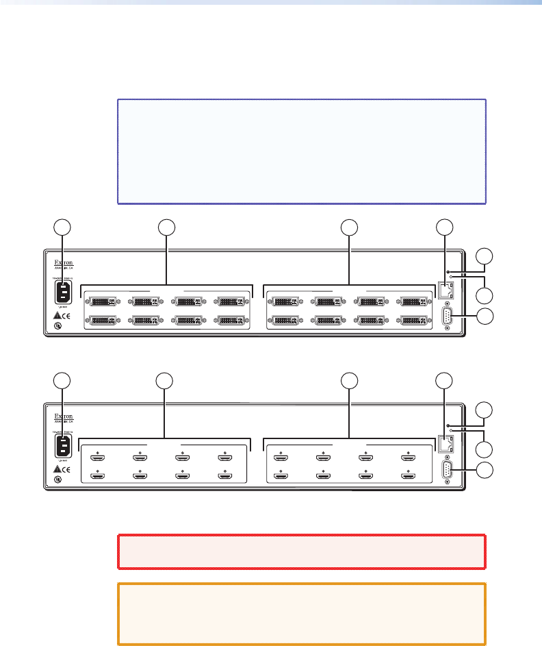
Most of the connectors are on the rear panels of the DXP switchers.
The following figures show the rear panels of the four DVI models
and the four HDMI models.
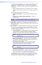
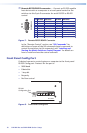
NOTE: The illustrations below show DXP 88 DVI Pro and
DXP 88 HDMI models, with 8 input and 8 output connectors.
The rear panels of the other DXP models are identical to
these models except for the number of inputs and outputs
(see "About the DXP DVI Pro and DXP HDMI Series Matrix
Switchers" in the "Introduction" section for the available
matrix sizes).
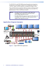
Figure 3. DXP DVI Pro Rear Panel
Figure 4. DXP HDMI Rear Panel
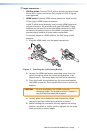
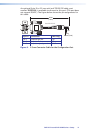
WARNING: Remove power from the system before making any
connections.
CAUTION: Use electrostatic discharge precautions (be
electrically grounded) when making connections.
Electrostatic discharge (ESD) can damage equipment,
although you may not feel, see, or hear it.
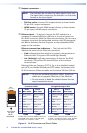
a
AC power connector — Plug a standard IEC power cord into this
connector to connect the switcher to a 100 VAC to 240 VAC, 50 or
60 Hz power source.
DVI-D INPUTS
LISTED
1T23
I.T.E.
C
U S
78
13
5
24
6
DVI-D OUTPUTS
DVI PRO - HDCP COMPLIANT
78
13
5
24
6
RESET
LAN
LINKACT
RS232/RS422
REMOTE
1
3
4
7
5
6
2
HDMI INPUTS
LISTED
1T23
I.T.E.
C
U S
78
13
5
24
6
HDMI OUTPUTS
HDMI - HDCP COMPLIANT
78
13
5
24
6
RESET
LAN
LINKACT
RS232/RS422
REMOTE
1
3
4
7
5
6
2