8 DXP DVI Pro and DXP HDMI Series • Setup
c
Output connectors —
NOTE: The switchers do not alter the video signal in any way.
The signal that is output by the switcher is in the same
format as the input signal.
• DVI Pro series: Connect DVI output devices to these female
29-pin DVI-I output connectors.
• HDMI series: Connect HDMI output devices to these female
19-pin type A HDMI output connectors.
d
Ethernet port — If desired, connect the DXP switcher to a
computer, a network WAN or LAN hub, or a control system via
this RJ-45 connector. With the Ethernet connection, you can use a
computer to control the networked switcher with SIS commands,
the Matrix Switchers Control Program, or the embedded HTML
pages on the switcher.
Ethernet connection indicators — The Link and Act LEDs
indicate the status of the Ethernet connection.
• Link: Indicates that the switcher is properly connected to an
Ethernet LAN. This green LED should light steadily.
• Act (Activity): Indicates transmission of data on the RJ-45
connector. This yellow LED should flicker as the switcher
communicates.
Ethernet links use Category (CAT) 3, 5e, or 6 unshielded twisted
pair (UTP) or shielded twisted pair (STP) cables, terminated with
RJ-45 connectors. Ethernet cables are limited to 328 feet (100 m).
NOTES: • Do not use standard telephone cables. Telephone
cables do not support Ethernet or Fast Ethernet.
• Do not stretch or bend the cables because this can
cause transmission errors.
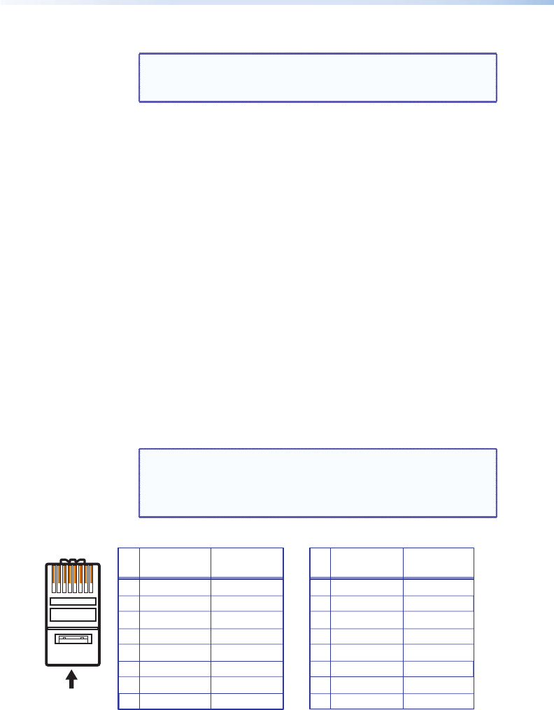
A cable that is wired as T568A at one end
and T568B at the other (Tx and Rx pairs
reversed) is a "crossover" cable.
A cable that is wired the same at both ends
is called a "straight-through" cable, because
no pin or pair assignments are swapped.
RJ-45
Connector
Insert Twisted
Pair Wires
12345678
Pins:
Crossover Cable Straight-through Cable
Pin
1
2
3
4
5
6
7
8
Wire Color
White-green
Green
White-orange
Blue
White-blue
Orange
White-brown
Brown
Wire Color
T568A
T568B
End 1 End 2 End 1 End 2
White-orange
Orange
White-green
Blue
White-blue
Green
White-brown
Brown
Pin
1
2
3
4
5
6
7
8
Wire Color
Blue
White-blue
White-brown
Brown
Wire Color
T568B
T568B
White-orangeWhite-orange
OrangeOrange
White-greenWhite-green
Blue
White-blue
GreenGreen
White-brown
Brown
Figure 6. RJ-45 Connector and Pinout Tables


