


DVS 510 Series • Installation 7
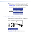
5. Connect power to the DVS by plugging a standard IEC power cord (provided) from a
100 to 240 VAC, 50-60 Hz AC power source into the power receptacle (
a
).
6. Configure the DVS 510 using the SPPCP (see the control program help file), SIS
commands (see the “Remote Configuration and Control” section, beginning on
page 47), the web pages (see the “HTML Configuration and Control” section,
beginning on page 85), or any combination of these methods.
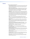
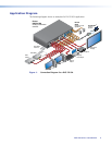
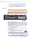
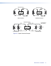
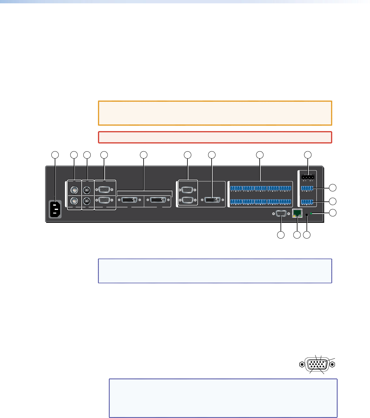
Rear Panel
The illustration below shows the connectors and indicators on the DVS 510 Series rear panel.
CAUTION: Use Electrostatic discharge precautions (be electrically grounded) when
making connections. Electrostatic discharge (ESD) can damage equipment,
although you may not feel, see, or hear it.
WARNING: Remove power from the system before making any connections.
100-240V 50-60 Hz
2A MAX
LAN
RESET
RS232
VID
VID
YC
RGB/R-Y, Y, B-Y
RGB/R-Y, Y, B-Y
RGB/R-Y, Y, B-Y
RGB/R-Y, Y, B-YYC DVI-I
DVI-D
AMPLIFIED
DVI-I
1
2
3
4
5
67/8 9/10
V
I
D
E
O
I
N
P
U
T
V
I
D
E
O
O
U
T
P
U
T
A
U
D
I
O
I
N
P
U
T
A
U
D
I
O
O
U
T
P
U
T
1
LR
LR
VARIABLE
LR
FIXED
LR
3
LR
5
LR
7
LR
9
LR
2
LR
4
LR
6
LR
8
LR
10
LR
10
9
1
2
3
4
5
6
8
7
11
12
1314
15
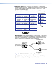
Figure 2. DVS 510 SA Rear Panel
NOTE: The illustration above shows the rear panel of a DVS 510 SA. The DVS 510
rear panel is identical except that it does not have the Amplified audio output
connector (
i
).
a AC power connector — Plug a standard IEC power cord from a 100 to 240 VAC,
50 Hz or 60 Hz power source into this IEC connector.
b Video inputs 1 and 2: Composite video — Connect one or two composite video
sources to these female BNC connectors.
c Video inputs 3 and 4: S-video — Connect one or two S-video sources to these female
4-pin mini-DIN connectors.
d Video inputs 5 and 6: buffered RGB or YUV component — Connect
one or two RGBHV, RGBS, RGsB, RGBcvS, YUVi, or YUVp/HDTV video
sources to these female 15-pin HD connectors (shown at right). These
inputs feature EDID emulation.
NOTE: (Optional) To obtain one or two additional RGB/YUV inputs, you can connect
an Extron DVIIM-VGAF/DVIIF DVI and Analog Breakaway (Y) cable to either
or both DVI-I input connectors. Each Y cable provides an additional RGB
VGA connector and DVI-I connector (see ”Breakaway cable” under
e
“Video inputs 7/8 and 9/10” on the next page for more information).
1
2
13
3
14