


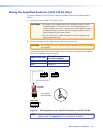
DVS 510 Series • Installation 8
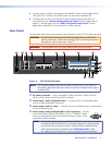
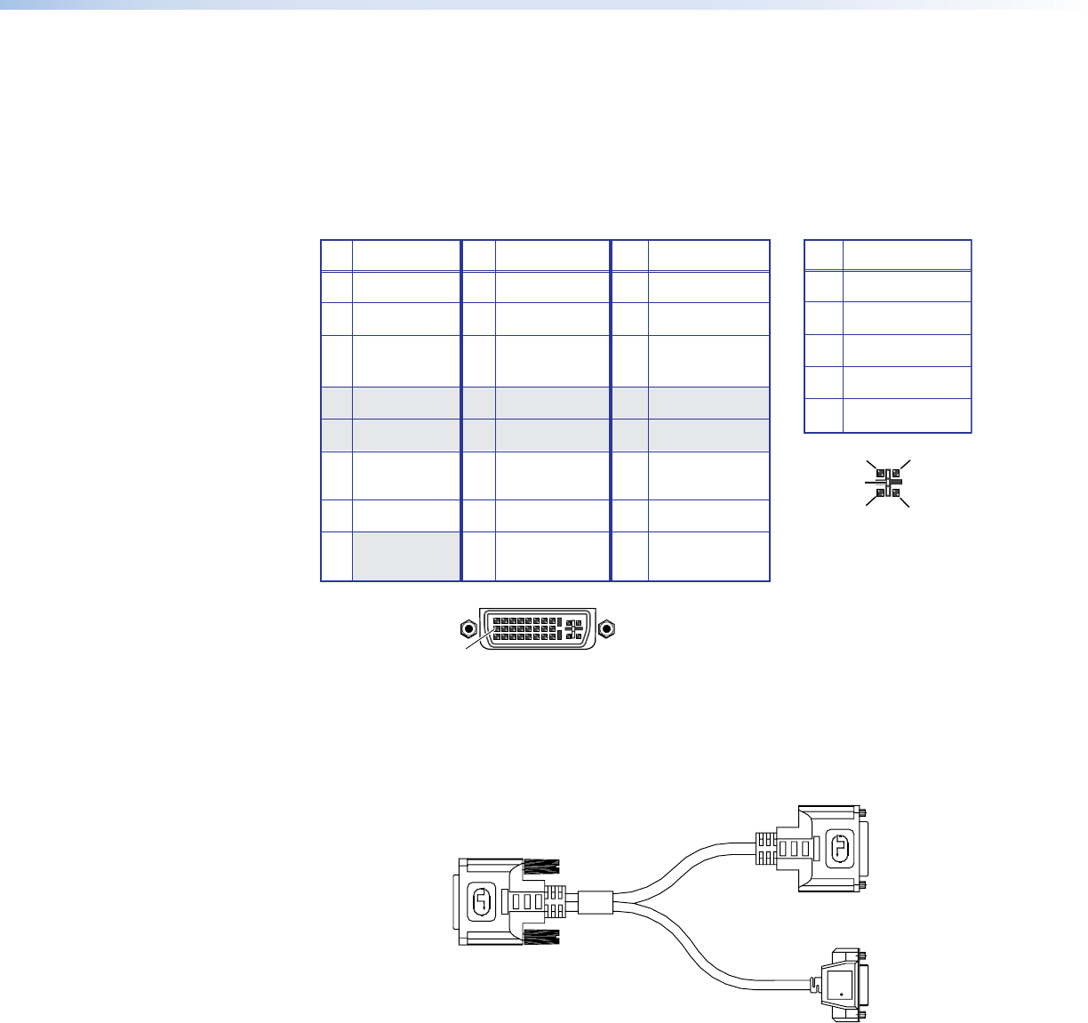
e Video inputs 7/8 and 9/10 — Connect two DVI, two RGB/YUV, or one each video
sources to these DVI-I connectors. The analog portions of these connectors are identified
as inputs 7 and 9, while the DVI portions are recognized as inputs 8 and 10. These
connectors feature EDID emulation.
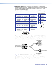
The following tables show the DVI-I connector pin assignments for DVI and analog
source connection.
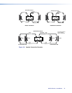
Pin
Signal
Pin Signal
Pin
Signal
1 TMDS data 2– 9 TMDS data 1– 17 TMDS data 0–
2 TMDS data 2+ 10 TMDS data 1+ 18 TMDS data 0+
3 TMDS data 11 TMDS data 1/3 19 TMDS data 0/5
2/4 shield shield shield
4 Not used 12 Not used 20 Not used
5 Not used 13 Not used 21 Not used
6 DDC clock 14 +5 V power 22 TMDS clock
shield
7 DDC data 15 Ground 23 TMDS clock+
1
8
17
24
9
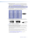
Digital Connections
C1
C4
C2
C3
C5
Pin
Function
C1
C2
C3
C4
C5
Red signal
Green signal
Blue signal
Horizontal sync
Ground
Analog Connections
8 Not used 16 Hot plug 24 TMDS clock–
detect
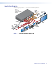
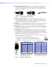
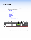
Breakaway cable: You can use an optional Extron DVIIM-VGAF/DVIIF “Y” DVI adapter
cable (shown below) to connect one analog RGB or YUV source and one DVI source to
one or both of these connectors. This cable enables both an analog and a DVI source
device to be connected to these ports and active at the same time.
Extron
DVI-I Male Connector
15-pin HD
Female Connector
FOR ANALOG ONLY
DVI-I Female Connector
FOR DIGITAL ONLY
To
DVS 510 Female
D
VI-I Input Connector
(Input 7/8 or 9/10)
To a DVI
Input Source
To an RGB or YUV
Analog Input Source
Figure 3. DVIIM-VGAF/DVIIF DVI and Analog Breakout Cable
(See the DVI Analog Breakout Adapter Instruction Card, part number 68-1172-01,
[provided with the adapter], for pin assignments for this Y cable.)