


IPI 100 and IPI 200 Series • Installation
2-2
Instaation
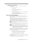
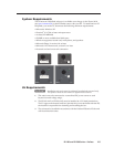
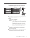
IPI Rear Pane Features and Cabing
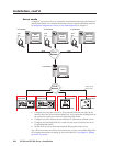
POWER RELAY
C NO
AUDIO OUT
LAN
Power
Contact
Relay
Audio Out
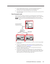
IPI 104 AAP, IPI 101 AAP
Rear Panel
AAP Mounting Screws (4)
Intercom Port
1a
2
IPI 204 AAP, IPI 201 AAP
Rear Panel
LAN Port
1b
AAP Mounting Screws (4)
2
3
4
5
Ä
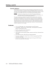
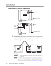
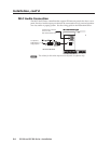
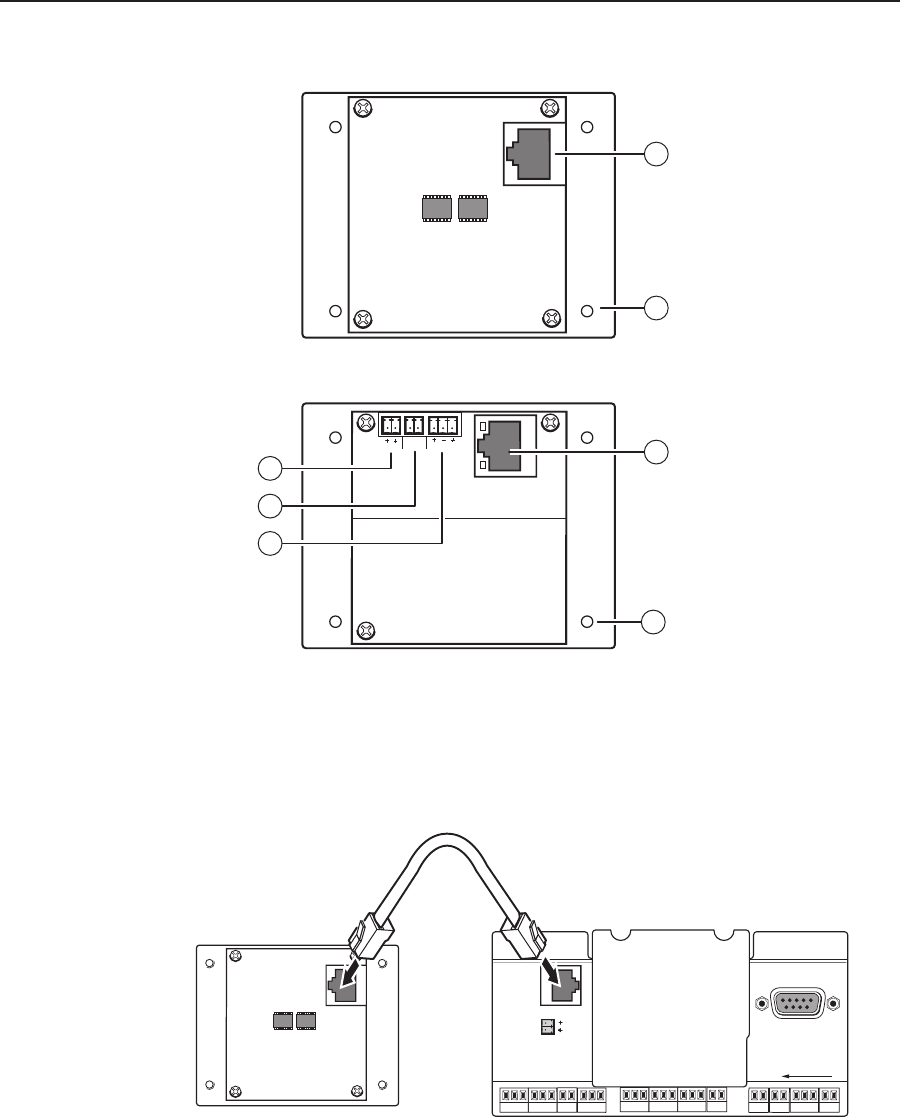
Intercom port(IPI101AAPandIPI104AAPonly)—Thisportisusedforpower,
control, and voice data communication with the MLC. Plug one end of a standard,
straightthrough,CAT5,CAT5e,orCAT6cableterminatedwithRJ‑45connectors
into this port. Plug the other end of the cable into the Intercom connector on the
MLC226IP’srearpanel,asshowninthefollowinggure.
HOST
CONTROL
R
1=DIGITAL I/O
2=Tx 3=Rx 5=GND
38400, N, 8, 1
PRESS TAB WITH
TWEEKER TO REMOVE
INTERCOM
AUDIO
OUT
LAN
IPI 101 AAP or IPI 104 AAP
Rear Panel
MLC 226 IP Rear Panel
<100’ (30.4 m)
C
This is not an Ethernet LAN connection. Do not connect these ports to
the Ethernet.
N
A 12 inch (30.5 cm) CAT 6 cable is included with each IPI. If you choose to
terminate your own cable, the cable must be no longer than 100 feet (30.4 m).
Cables must be terminated to the T586A or T586B standard and both ends of a
cable must be wired to the same standard (see cable wiring on the next page).