


2-3
IPI 100 and IPI 200 Series • Installation
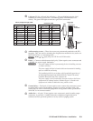
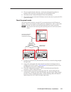
Å
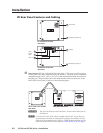
LAN port(IPI201AAPand204AAPonly)—PluganRJ‑45jackintotheLAN
connectortoconnecttoanetwork.TheblinkingyellowLEDindicatesLAN
activity.ThegreenLEDlightstoindicateagoodLANconnection.
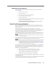
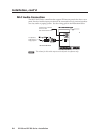
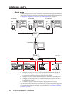
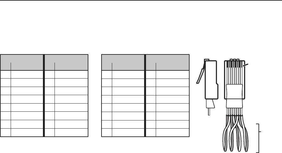
Patch (straight-through) cable
Side 1 Side 2
Pin Wire color Pin Wire color
1 White-orange 1 White-orange
2 Orange 2 Orange
3 White-green 3 White-green
4 Blue 4 Blue
5 White-blue 5 White-blue
6 Green 6 Green
7 White-brown 7 White-brown
8 Brown 8 Brown
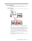
Crossover cable
Side 1 Side 2
Pin Wire color Pin Wire color
1 White-orange 1 White-green
2 Orange 2 Green
3 White-green 3 White-orange
4 Blue 4 Blue
5 White-blue 5 White-blue
6 Green 6 Orange
7 White-brown 7 White-brown
8 Brown 8 Brown
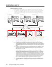
Clip Down
Side
1
1&2
3&6
4&5
7&8
2345678
Pins
12345678
RJ-45
connector
Twisted
Pairs
b
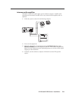
AAP mounting screws — ThesefourscrewsarepermanentlyattachedtotheIPI’s
faceplate. They are used for mounting the faceplate into another device (such as an
MLC226IPAAP)oramountingframe.
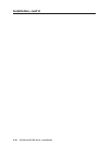
N
Items
c
to
e
apply only to the IPI 201 and IPI 204 models.
c
Power — Connectacablebetweenthe2‑pole,3.5,mmcaptivescrewconnectorand
a12VDC,1Apowersupply(included).
C
The power supply shall not be permanently fixed to the building structure
or similar structures.
The power supply shall not be located within environmental air handling
spaces or within the wall cavity.
The installation shall be in accordance with the applicable provisions of
the NationalElectricalCodeANSI/NFPA70,Article725 and the
CanadianElectricalCode,Part1,Section16.
The power supply is to be located within the same vicinity as the Extron
equipment in an ordinary location, Pollution Degree 2, secured to the
equipment rack within the dedicated closet, podium or desk.
d
Contact Relay — The 2‑pole,3.5,mmcaptivescrewcontact relay connector is used
to control items such as room lighting, window coverings, and door locks. The
contact may be used to control any equipment as long as the contact specifications
of24VDCat1Aarenotexceeded.
e
Audio Out — A3‑pole,3.5mmcaptivescrewconnectorisusedforaudiooutput
connection.Itprovidesa‑10dBVbalancedorunbalancedsignalthatcanbe
connected to local, powered speakers or to any audio or paging system.