184 Maintenance Manual RX900 S1
Main memory
9.1.3 Populating the CPUMEMR
Ê Populate the DIMM memory module slots by using the following procedures:
1. "Selecting the DIMM memory module slot" on page 192
2. "Inserting the DIMM memory module in the slot" on page 194
9.1.4 Selecting the CPUMEMR slot
Ê Choose the CPUMEMR slot according to the configuration rules
summarized in this section. For detailed information see "Baseboard D3081,
CPUMEMR D3131, PCIR D3082 for PRIMERGY RX900 S1 Technical
Manual".
The basic configuration includes four CPUMEMRs. This configuration can be
expanded in two steps. Each steps includes two additional CPUMEMRs. In the
4 and 6 CPUMEMR configurations, an air duct is installed in an empty slot as
indicated in table 3.
I Make sure that the selected CPUMEMR configuration enables you to use
the PCIe slots needed for the individual use case of the server. For the
assignment of CPUMEMRs to PCIe slots see "PCIe slot to CPUMEMR
assignment" on page 362.
Figure 106 shows the CPUMEMR slots #1- #8 (from bottom to top). The slots
populated in the basic configuration are indicated by the blue color.
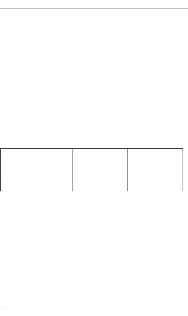
Number of
CPUMEMRs
Population
order
CPUMEMR position Air duct position
4 1 #1 + #2 + #3 + #4 #6
6 2 #5 + #6 #8
8 3 #7 + #8 --
Table 3: Population order for CPUMEMRs


