


Magnum 3000 Stackable Hubs Installation and User Guide (07/06)
10
www GarrettCom com
..
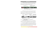
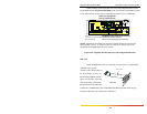
NOTE: To differentiate the SRC cable from the IRB cable, GCI uses colored
ribbon cable for the SRC. The standard IRB cables are gray in color.
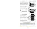
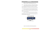
2.3.3 Group # Address Switch Settings, for Managed Units and Stacks
The eight-position DIP switch on the rear panel is used to give each unit in a
Magnum 3000 managed stack a unique Group # or "stack address". This Group #
follows the SNMP definition. (Group # addresses and the associated switch settings do
not matter if the units are unmanaged or "dumb"). See the illustration in Figure 2.3.3a.
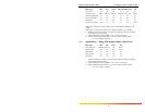
Switches one through six are set at the time of installation to form a binary
number from 1 to 20. The switch positions may be moved using an instrument such as a
small screw driver, a pencil eraser or a fingernail. See Section 5.3 for a table of switch
settings vs. Group # address numbers.
The units in a managed stack should have Group # addresses beginning at 1
and proceeding up to the number of stacked units configured as one logical repeater at
the particular installation. The factory default address switch setting is usually "1", i.e.,
switch 1 ON and switches 2 through 6 OFF.
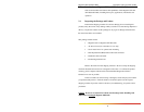
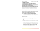
Figure 2.3.3a, Group # Address Switches, Enlarged Illustration
1 2 3 4 5 6 7 8
ON
OFF
Group # ADDRESS SWITCHES