


Magnum 3000 Stackable Hubs Installation and User Guide (07/06)
37
www GarrettCom com
..
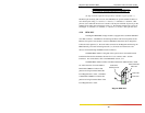
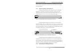
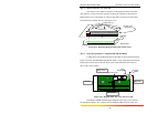
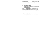
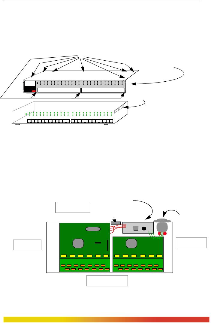
Step 1. Remove Chassis Cover of the hub
The chassis cover is made in one piece, forming the top and the front of the
unit. There are 7 screws located on top and 3 on the front of the unit as shown below.
Remove these screws. Once these are removed, the chassis cover/front is easily lifted
forward and off of the chassis base. (See Figure 5.3a).
Figure 5.3a: Removing Magnum 3024 / 3012 Chassis Cover
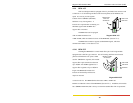
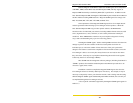
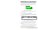
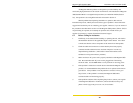
Step 2. Insert the Agent Board (Magnum 3024 and 3012 Hubs)
Looking down into the Magnum 3024 or 3012 hub as shown in the illustration
Figure 4.3c below, the Embedded Agent Board mounts on top of the other printed circuit
boards in the left-rear area of the unit. Three screws with stand-offs hold it firmly in
place in the correct position.
Figure 5.3b: Magnum 3024, Top View with Cover Off
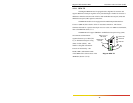
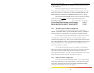
The Magnum SNMP embedded agent daughter board, Figure 4.3d, connects
into the DB-9 connector "P1" on the back of the Magnum 3000 unit with a cable, and
One piece cover,
top and front
10 Phillips Head Screws
Magnum 3024
Ventilation
Slots
Chassis Cover
Magnum 3000
Stackable Hub
GARRETT
1 2 3 4 5 6 7 8 9 10 11 1213 14 15 16 17 18 19 20 21 22 23 24
Back of Unit
Front of Unit
Right Side
Left Side
Power Supply
AC Power
Input
Optional Bonus Port