


Magnum 3000 Stackable Hubs Installation and User Guide (07/06)
14
www GarrettCom com
..
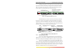
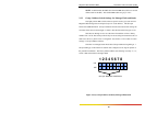
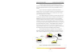
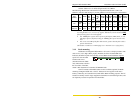
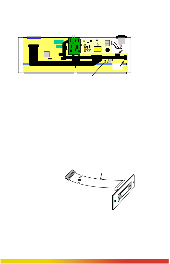
When installing a PM into the Bonus Port slot of the Magnum 3024, use the
16-pin header labeled P1 (also labeled RPM) on the circuit board corresponding to ports
13-24. The red stripe of the connector cable should connect to pin 1 of header P1.
NOTE: The PM will still function if connected to header J1/B of the circuit board
corresponding to ports 1-12. However, this is not advised, as the port will not be
recognized by an SNMP Agent (if one is present).
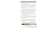
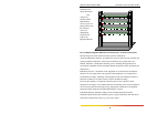
Figure 2.5d: Magnum 3024 internal layout with configured Bonus Port
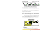
CBL-AUI
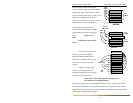
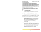
When the RPM-AUI is factory configured as a bonus port, it is implemented
with CBL-AUI, an AUI
connector with a ribbon cable, to
the 16-pin header J1 (AUI) on
the main board (Shown in both
figure 2.5a and 2.5b). Since the
AUI functionality is build onto
the main board, using CBL-AUI
is identical to the RPM-AUI. GCI recommends that RPM-AUI units should not get
installed in the bonus port of both 3012’s and 3024’s.
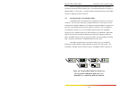
Bonus
p
ort for o
p
tional
PM card
(
BPM shown
)
PM Ribbon cable with 16 pin connector.
(Included only when PM is factory
Ma
y
be ordered se
p
aratel
y
as
p
art # CBL-PM)
NOTE:
Use J1 (AUI) and for Basic AUI ports
Use P1 (RPM) for PMs
J1
(AUI)
P1
(RPM)
Pin 1 (red)
CBL-AUI