


Magnum 3000 Stackable Hubs Installation and User Guide (07/06)
51
www GarrettCom com
..
C5.0 INSTALLATION
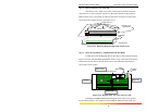
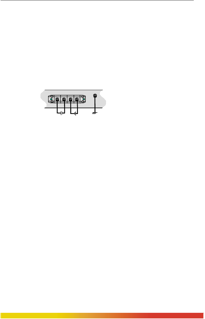
This section describes the proper connection of the -48VDC, 24VDC &
125VDC dual source leads to the –48 VDC, 24VDC and 125VDC power terminal block
on the Magnum 3000s (shown in Figure C5.0 )
The -48VDC terminal block on the Magnum 3000s, as shown in Fig C5.0 is
located on the left rear of the unit and is equipped with five (5) screw-down lead posts.
The primary terminals are identified as positive (A+), negative (A-), and the secondary
power terminals as negative (B-), positive (B+). The chassis “earth” or ground (GND), is
a threaded post with a #6 nut. The Dual source terminal blocks for 24VDC and 125VDC
are similar.
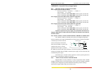
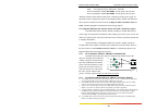
Figure C5.0: -48VDC Dual-Source, wiring connections to the External Terminal
Block on a Magnum -48VDC with Dual-Source option
Note: The GND should be hooked up first. The 3000s unit has a floating ground, so
the user may elect to Ground either + or = terminal to suit the customer’s use.
Before connecting hot lines to the Terminal Block of –48VDC, 24VDC or
125VDC, always use a digital voltmeter to measure the output voltage of the power
supply and determine the lead which is more “+ve Potential”. The more “+ve” voltage
lead from 48V or –48V Power supply must be connected to the post labeled “+”.
The connection procedure is straightforward. Simply connect the DC leads to
the 3000’s power terminals, positive (+) and negative (-) screws. The use of Ground
(GND) is optional; it connects to the 3000s chassis. Ensure that each lead is securely
tightened.
The 24VDC & 125VDC terminal block on Magnum 3000s is similar to that
described in the –48VDC info above.
C5.1 UL Requirements
The following must be adhered to in order to conform to UL requirements:
1. Minimum 14 AWG cable for connection to a Centralized DC power source.
2. Fastening torque of the lugs on the terminal block: 9 inch pound max.
3. Centralized DC Power Source cable securement, use at least four cable ties to
secure the cable to the rack at least 4 inches apart with the first one located
within 6 inches of the terminal block.
36-70VDC
GND
A+ A- B- B+
36-70VDC