


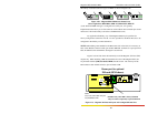
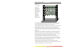

Magnum 3000 Stackable Hubs Installation and User Guide (07/06)
17
www GarrettCom com
..
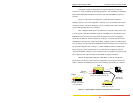
3.0 Installation and Operation
Before installing the equipment, it is necessary to take the following precautions:
1) If the equipment is mounted in an enclosed or multiple rack assembly, the
environmental temperature around the equipment must be less than or equal to 50C.
2) If the equipment is mounted in an enclosed or multiple rack assembly, adequate air flow
must be maintained for proper and safe operation.
3) If the equipment is mounted in an enclosed or multiple rack system placement of the
equipment must not overload or load unevenly the rack system.
4) If the equipment is mounted in an enclosed or multiple rack assembly, verify the
equipment’s power requirements to prevent overloading of the building/s electrical circuits.
5) If the equipment is mounted in an enclosed or multiple rack assembly verify that the
equipment has a reliable and uncompromised earthing path.
6) If the intra-building wiring (cabling) is involved with this product(NEBS), then it is
recommended to have shielded cable and the shield is grounded at both ends.
7) This equipment is for installation only in a Restricted Access Location (dedicated
equipment room service closet and the like) in accordance with the National Electrical
Code.
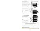
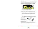
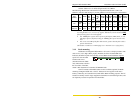
3.1 Connecting Ethernet Media
The Magnum 30000 Hubs are specifically designed to support all Ethernet
media types via the Bonus Port options. There is a family of Port Modules (PMs). The
procedures for connecting each media and connector type are as follows:
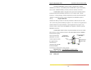
3.1.1 Connecting Twisted Pair (RJ-45, Unshielded or Shielded)
The following procedure describes how to connect a 10BASE-T twisted pair
segment to the RJ-45 port on the front panel of the 3000 hub or to the RPM-TP or BPM-
TP of the 3000X or bonus port. The procedure is the same for both unshielded and
shielded twisted pair segments.
1. Using standard 10BASE-T media, insert either end of the cable with an RJ-45
plug into the RJ-45 connector. Note that, even though the TP connector is
shielded, either unshielded or shielded 10BASE-T cables and wiring may be
used.
2. Connect the other end of the cable to the corresponding device.
3. When proper connection and power have been established, the port’s LINK LED
will illuminate GREEN.
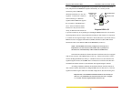
NOTE: The Magnum RPM-TP and BPM-TP are equipped with a cross-over slide
switch to accommodate repeater-to-repeater connections without special cross-
over connectors. Set the slide switch to the “down” position for normal twisted
pair cable segments from the hub port to a user device. Set the slide switch to
the “up” position for cascaded or up-link segment connections to another
repeater or hub in the network. Verify proper switch position by noting that the
port’s LINK LED will illuminate when proper link is established.