


Magnum 3000 Stackable Hubs Installation and User Guide (07/06)
11
www GarrettCom com
..
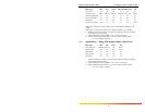
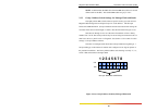
The Group # switch settings must not be the same for any two Magnum 3000
units operating in one managed stack. Factory default switch settings cannot be relied
upon, and the user must check and/or change the Group # address switch settings for
each managed Magnum 3000 unit installed.
If a network management software package is in use, the Group # addresses set
for each Magnum 3000 physical unit will be reflected in the NMS displays, statistics and
controls that correspond to that unit's Group # address. (While non-sequential Group #
addresses will not prevent the units in a stack from working properly in the network, such
numbering tends to create problems for network administration and are therefore
discouraged accordingly.)
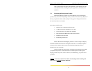
A Magnum 3000 stack may have from 2 to 20 active units (not including an
optional 3000-AGT unit, which could be the 21st box in a large stack). The stacked units
may be any combination of Magnum 3024s, 3012s,3000X and they may be arranged in
any order, physically and logically, for Group numbering purposes. Switch settings for
Group # addresses of zero and from 21 to 31 are not recognized by the NMS software in
a managed system, and the use of such Group # addresses is discouraged.
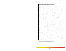
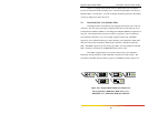
Switch 7 of the eight-position DIP switch is no longer used. In previous
versions of the product line it allowed the use of a PC-based SNMP AGENT. Switch 8
of the eight-position DIP switch is also unused.
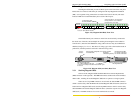
The "P1" DB-9 connector on the upper part of the rear panel is used for a serial
port into the optional embedded SNMP agent board. If there is no embedded agent board
in a unit, "P1" is not present. See Section 5.1 for operational information on the optional
SNMP embedded agent board.
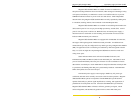
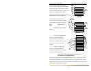
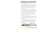
2.4 Magnum 3012 Hub - 12 RJ-45 Ports, One PM bonus port slot
The Magnum 3012 Hub provides 12 shielded RJ-45 ports on the front of the
unit, and is otherwise like the Model 3024 described above. Refer to the descriptive
material in Section 2.3 above.
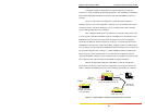
Figure 2.4a, Magnum 3012 Hub, Front View
Ma
g
num 3000
Stackable Hub
GARRETT
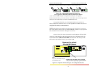
Two LEDs (RX & LINK)
for each RJ-45 10BASE-T port.
Twelve RJ-45 10BASE-T Ports
LINK
RX
Steady On LINK LED = Port is Operational
Flashing LINK LED = Port is Partitioned
Flashing RX LED = Port Activity