


Magnum 3000 Stackable Hubs Installation and User Guide (07/06)
29
www GarrettCom com
..
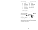
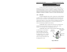
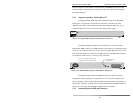
Important Note: For the RPM-TP MDI-X Crossover Switch -
DOWN(or Right) for workstations and user connections.
UP (or Left) for Up-Link connections to other hubs, etc.
(To help recall the right TP switch position, remember "up for up-link" ! )
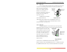
The RJ-45 pins normally (TP crossover switch DOWN) are per the standard for hubs-to-
users twisted pair wiring: 1 = receive+, 2 = receive-, 3 = transmit+, 6 = transmit-, other
pins not used. When the TP crossover switch is UP, the pins of the RJ-45 port are per the
standard for up-links using twisted pair wiring, i.e., the transmit and the receive pairs are
exchanged: 1 = transmit+, 2 = transmit-, 3 = receive+, 6 = receive-, other pins not used.
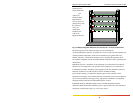
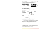
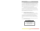
4.2.8 BPM-BNC
The Magnum BPM-BNC bridge module is equipped with a standard 10BASE2
coax BNC connector. This BPM is self-learning and filters and forwards packets at full
Ethernet wire speed. This module is used for 10BASE2 connections and is designed to
isolate the local segment (i.e., the local nodes connected to the Magnum unit housing the
BPM internally) from the connecting network (i.e., the nodes of external users and
devices connected through the BPM’s media connector).
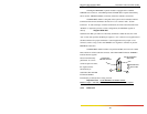
The BPM-BNC module is designed with a special switch -selectable internal
termination function that eliminates the need for a "tee" connector and a 50 ohm
terminator. For switch details, refer to the RPM-BNC section, 3.2.1
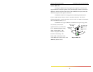
The BPM-BNC module includes an FWD-I LED and an FWD-X LED, which
are visible from the front. The FWD-I
LED blinks GREEN to indicate that
packets are being forwarded INTO the
local Magnum hub or stack.. The FWD-
X LED blinks GREEN to indicate that
packets are being forwarded OUT of the
local Magnum hub or stack.
Magnum BPM-BNC
Standard BNC
10BASE2 Connector
Internal Termination
Slide Switch
1
2
FWD-X LED
FWD-I LED
2
1