


640t – Installation and Operating Instructions
Page 5-2
id l e r Ba r s , un W i n d sh a f t s ,
re W i n d sh a f t s
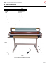
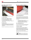
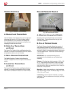
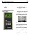
Fig. 5-3. Idler Bars, Unwind Shafts, Rewind Shafts.
a. up p e r re W i n d
B. up p e r un W i n d /su p p ly sh a f t
c. lo W e r un W i n d /su p p ly sh a f t
The Lower Idler directs Kraft Paper or images to the
Lower Main Roller.
d. up p e r id l e r
The Upper Idler directs the lm around the roller and
is used as a point of release when using PSA lms.
The release liner will be separated and redirected to
the Rewinder.
Not shown: Lower Idler Bar and Lower Rear Rewind
ro l l e r s a n d sa f e t y se n s o r
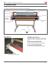
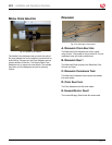
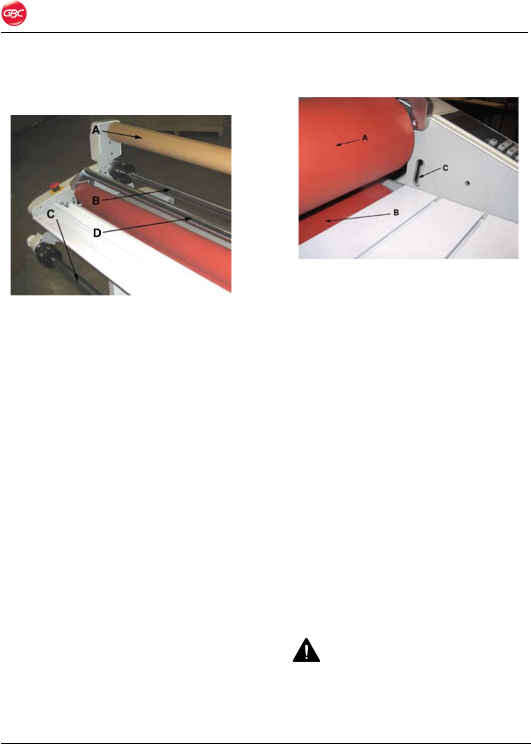
Fig. 5-4 Upper and Lower Main Rollers and Safety Sensor.
a. up p e r ma i n ro l l e r
The Upper Main Roller lowers onto the Lower Main
Roller to create the nip or the point at which the top
and bottom rollers come into contact and the point
at which the items to be laminated are introduced to
the laminator.
The Upper Main Roller is heated. The •
temperature is controlled by the Control Panel.
The Upper Main Roller can be raised or •
lowered using the Roller Pressure Handle.
B. lo W e r ma i n ro l l e r
The Lower Main Roller is driven and advances media
into the nip. The Lower Main Roller is not heated.
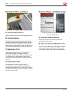
c. sa f e t y se n s o r
The Safety Photo Sensor prevents entanglement,
entrapment, and inadvertent contact with the
rollers. The sensors are located on each side of the
machine, in front of the bottom roller. They stop the
machine when a hand or object blocks the invisible
beam if you are not using the foot switch.
When the foot switch is used, the speed drops to 3
fpm (0.9 m).
WARNING: Keep your ngers and hands
away from the nip point. Failure to observe
this warning could result in severe personal injury.