


Page 6-3
640t – Installation and Operating Instructions
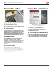
re m o v i n g a n d in s ta l l i n g t h e
p
r i n t cl a m p
The print clamp guides prints into the rollers. It
should be removed when mounting items to thicker
boards. It also needs to be removed to install lms
and when cleaning the rollers.
WARNING: Keep ngers and hands away from
the rollers when the machine is running. They could
be trapped and crushed in the rollers. Clothing,
jewelry, and long hair could be caught in the rollers
and pull you into them.
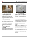
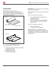
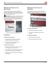
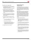
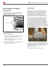
Fig. 6-4. Print Clamp and Release Latch.
A. Print Clamp
B. Release Latch
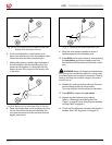
To remove the print clamp:
Slide and hold either the left or right latch 1.
towards the center of the laminator.
Lift the end of the print clamp up while 2.
disengaging the opposite end.
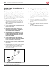
To install the print clamp:
Position one end of the print clamp so that its 1.
latch engages into its locking hole.
Lower the other end while retracting the latch so 2.
that the latch lines up with its locking hole.
Release the latch and ensure that both latches 3.
are engaged.
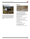
re m o v i n g a n d in s ta l l i n g t h e
f
e e d ta B l e
The feed table should not be removed except to
install lms. When the table is off, the laminator runs
at a xed speed of 3 fpm (0.9 m).
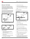
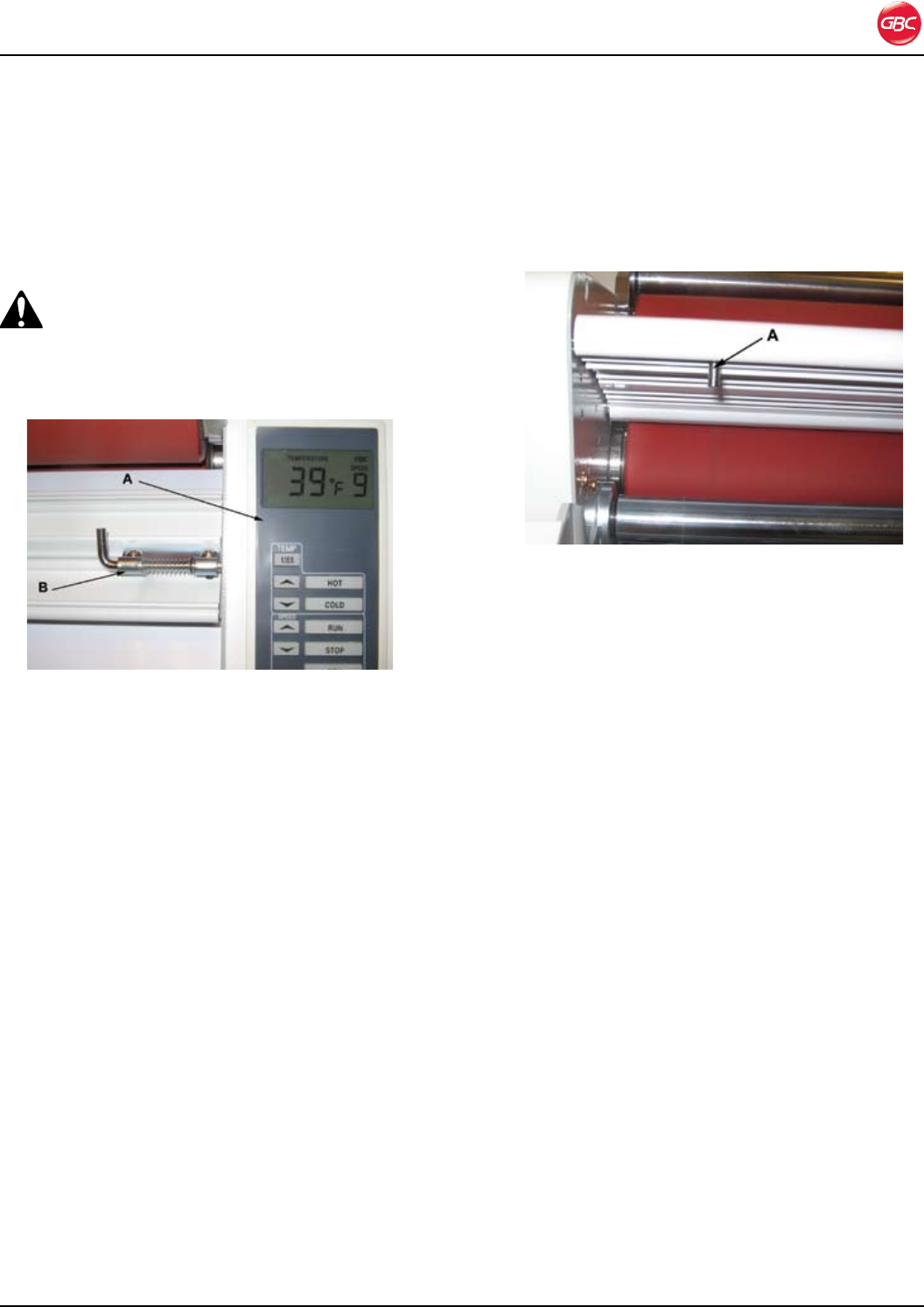
Fig. 6-5. Table Interlock Latch.
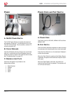
To remove the feed table:
Slide the feed table latch to the right.1.
Lift the table upwards and away from the 2.
laminator.
To install the feed table:
Place the table on the machine.1.
Slide the feed table latch to the left.2.