Page 6-5
640t – Installation and Operating Instructions
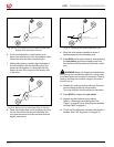
To load films onto the supply shafts:
If the supply shaft is on the machine, grasp the 1.
bearing end and lift it out of the cradle. Then pull
the left end out of the brake hub.
This applies to the top and bottom supply shafts.
Slide the new roll on to the shaft and core 2.
adaptors, referring to “Fig. 6-3. Poly-in and
Poly-out Films.” on page 6-2 to determine how
the film unwinds from the roll. Use the set screws
in the core adaptors to move the adaptors if
needed.
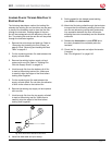
Insert the hex end of the shaft into its brake hub 3.
and then insert the bearing end in its cradle. See
“Fig. 6-7. Supply Shafts.” and “Fig. 6-8. Supply
Shaft Cradle End.”
Center each supply roll on the shafts by doing 4.
the following. Also see “Film Alignment” on page
6-10.
Use a ruler to measure from the left edge of a.
the roll to the left side frame.
Do the same on the right side. b.
Shift the roll side to side so that both c.
measurements are equal. It is important that
the edges of the films are aligned so that
adhesive does not stick to the rollers.
Center the take-up core on its shaft.5.
th r e a d i n g fi l m W i t h a
t
h r e a d i n g ca r d
The following procedure uses a lm threading card
that is sometimes provided with new rolls of lm. If
one is not provided, a scrap of cardboard or poster
board with a straight edge is suitable. Either can be
reused. Prior to loading lm, remove the print clamp
and feed table.
Note: These instructions are for loading laminating
and mounting lms for decaling. The top supply
shaft is used for laminating lms and the bottom
supply shaft is used for mounting lm or Kraft paper.
If you are not applying mounting lm to a laminate,
Kraft paper should be used on the bottom supply
shaft to prevent adhesive from sticking to the rollers.
For more information about loading lms for other
processes, refer to the appropriate section in this
chapter.
To web (load films) the machine:
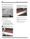
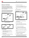
Remove the print clamp and feed tray. Refer to 1.
“Removing and Installing the Print Clamp” on
page 6-3 and
“Removing and Installing the Feed
Table” on page 6-3.
Pull the top film down, thread it under the idler 2.
bar, and pull the film back up to the take-up core.
Lightly tape both corners of the film to the 3.
take-up core. Ensure that the film is pulled evenly
and that no bulges exist at either end of the idler
bar.
Using a very sharp utility knife, lightly score the 4.
laminating film approximately 4 in (10 cm) above
the upper pressure roller. Be careful to not cut
through the release liner.
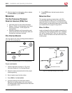
Pull the laminating film away from the liner and 5.
drape it over the front of the pressure rollers so
that it extends to a little past the bottom of the
top pressure roller.


