


Page 5-3
640t – Installation and Operating Instructions
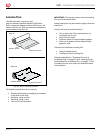
em e r g e n c y st o p a n d ta B l e
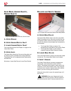
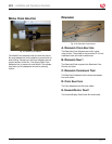
Fig. 5-5. Emergency Stop Button and Table Components.
a. ta B l e in t e r l o c k ho l e
When the table is down, the latch engages this hole.
B. ta B l e in t e r l o c k
The Table Interlock latch locks the feed table into
position and activates an interlock switch. The latch
is located on the left, underside of the feed table.
Move the latch to the right to release the table. Then
lift the table upwards and away from the laminator.
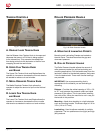
c. em e r g e n c y st o p
The Emergency Stop Switch is on the left side
of the 640t laminator. To engage, press the
Emergency Stop Switch and roller movement stops.
To disengage, turn the Emergency Stop Switch
clockwise once the emergency condition has been
resolved.
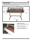
d. fr o n t fe e d ta B l e
The feed table is used to position items for
laminating and mounting. When the feed table is
removed, the laminator runs at 3 fpm (0.9 m) when
you press the foot switch. The feed table is removed
only when you load lm.
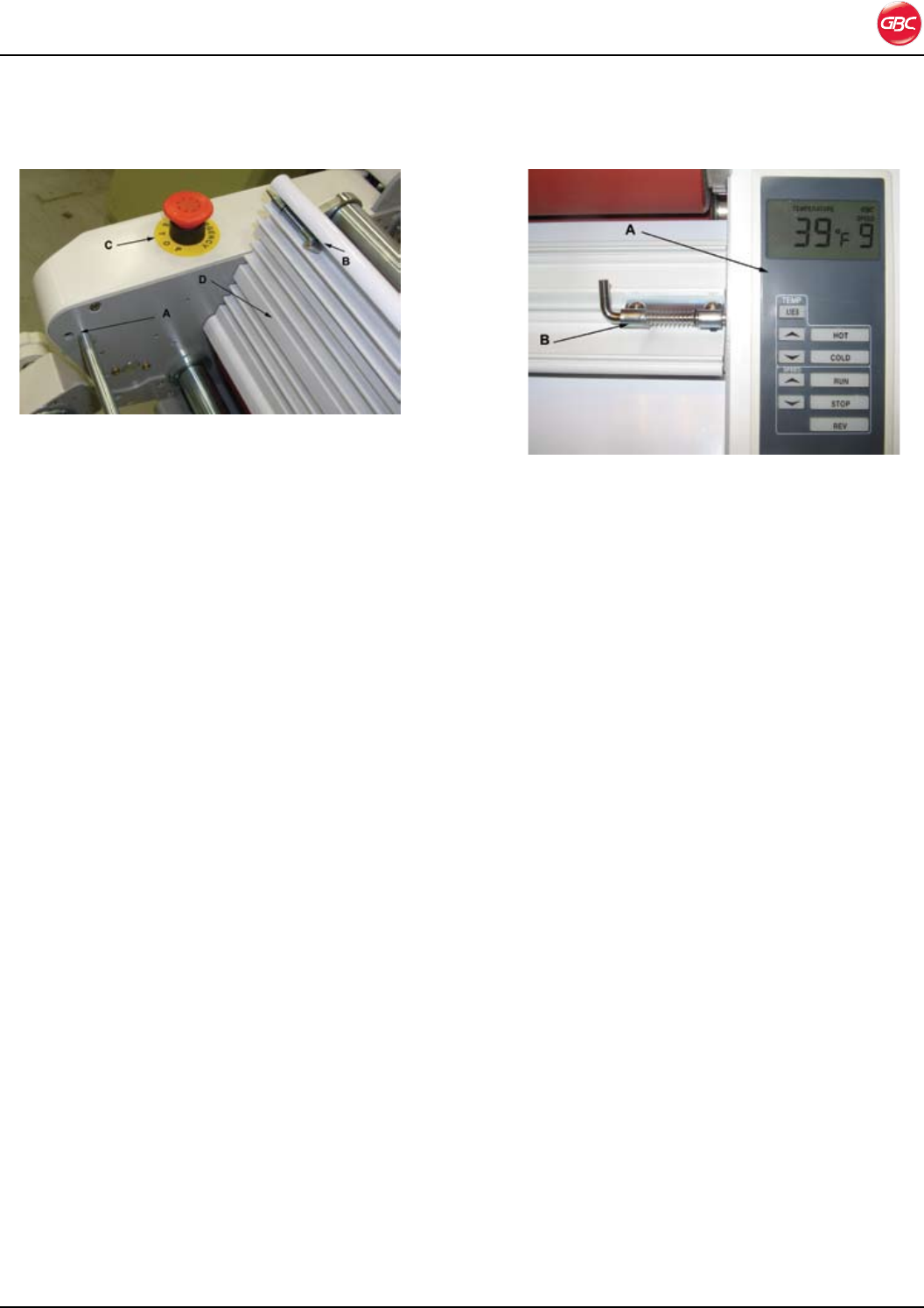
co n t r o l pa n e l a n d pr i n t cl a m p
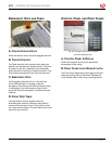
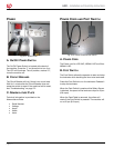
Fig. 5-6. Control Panel and Print Clamp
and Lock Release Latch.
a. co n t r o l pa n e l & di s p l a y
Allows the operator to control the speed and
temperature of the rollers.
B. pr i n t cl a m p lo c k re l e a s e la t c h
The Print Clamp helps keep prints against the feed
table while being fed into the rollers. Release the
Lock Release Latch when using mounting boards.