


10 MM200 MOTOR MANAGEMENT SYSTEM – COMMUNICATIONS GUIDE
RS485 INTERFACE (MODBUS RTU) COMMUNICATIONS GUIDE
Performing
Commands Using
Function Code 10H
Commands can be performed using function code 16 as well as function code 5. When
using FUNCTION CODE 16, the Command Function register must be written with a value of
5. The Command Operation register must be written with a valid command operation
number. The Command Data registers must be written with valid data; this is dependent
upon the command operation.
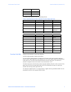
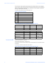
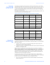
For example, consider a request for slave 17 to perform command operation 1 (RESET): The
master/slave packets have the following format:
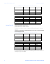
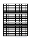
Table 9: MASTER/SLAVE PACKET FORMAT FOR PERFORMING COMMANDS
Using the User
Definable Memory
Map
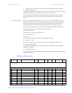
The MM200 contains a User Definable area in the memory map. This area allows re-
mapping of the addresses of any Actual Values or Setpoints registers. The User Definable
area has two sections:
1. A Register Index area (memory map addresses 020BH-0287H) that contains 125
Actual Values or Setpoints register addresses.
2. A Register area (memory map addresses 020BH-0287H) that contains the data at the
addresses in the Register Index.
Register data that is separated in the rest of the memory map may be re-mapped to
adjacent register addresses in the User Definable Registers area. This is accomplished by
writing to register addresses in the User Definable Register Index area. This allows for
improved throughput of data and can eliminate the need for multiple read command
sequences. The User Definable Register Index is stored as a setpoint and therefore it is
“remembered” even when the power is removed.
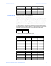
For example, if the values of MOTOR LOAD (register address 014FH; modbus address
30336) and DRIVE STATUS (register address 0135H; modbus address 30310) are required to
be read from a MM200, their addresses may be re-mapped as follows:
1. Write 30336 to address 020BH (40524) (User Definable Register Index 0000) using
function code 06 or 16.
MASTER TRANSMISSION BYTES EXAMPLE DESCRIPTION
SLAVE ADDRESS 1 11 message for slave
17
FUNCTION CODE 1 10 store multiple
setpoints
DATA STARTING ADDRESS 2 00 80 setpoint address
00 80
NUMBER OF SETPOINTS 2 00 02 2 setpoints = 4
bytes total
BYTE COUNT 1 04 4 bytes of data
DATA 1 2 00 05 data for address
00 80
DATA 2 2 00 01 data for address
00 81
CRC 2 7E CE CRC error code
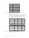
SLAVE RESPONSE BYTES EXAMPLE DESCRIPTION
SLAVE ADDRESS 1 11 message from
slave 17
FUNCTION CODE 1 10 store multiple
setpoints
DATA STARTING ADDRESS 2 00 80 setpoint address
00 80
NUMBER OF SETPOINTS 2 00 02 2 setpoints
CRC 2 42 B0 CRC error code