


2 MM200 MOTOR MANAGEMENT SYSTEM – COMMUNICATIONS GUIDE
RS485 INTERFACE (MODBUS RTU) COMMUNICATIONS GUIDE
RS485 interface (Modbus RTU)
The RS485 interface is a serial two-wire port intended for use as a Modbus RTU slave. The
RS485 port has the following characteristics.
• Address: 1 to 254
• Baud rate: 9600 to 115200 bps
• Supported Modbus function codes: 3, 4, 5, 6, 7, 8, 16
Modbus Protocol
The MM200 implements a subset of the Modicon Modbus RTU serial communication
standard. The Modbus protocol is hardware-independent. That is, the physical layer can be
any of a variety of standard hardware configurations. This includes RS232, RS422, RS485,
fibre optics, etc. Modbus is a single master / multiple slave type of protocol suitable for a
multi-drop configuration as provided by RS485 hardware. The MM200 Modbus
implementation employs two-wire RS485 hardware. Using RS485, up to 32 MM200s can be
daisy-chained together on a single communication channel.
The MM200 is always a Modbus slave. It can not be programmed as a Modbus master.
Computers or PLCs are commonly programmed as masters.
Both monitoring and control are possible using read and write register commands. Other
commands are supported to provide additional functions.
Electrical Interface The hardware or electrical interface in the MM200 is two-wire RS485. In a two-wire link,
data is transmitted and received over the same two wires. Although RS485 two wire
communication is bi-directional, the data is never transmitted and received at the same
time. This means that the data flow is half duplex.
RS485 lines should be connected in a daisy chain configuration with terminating networks
installed at each end of the link (i.e. at the master end and at the slave farthest from the
master). The terminating network should consist of a 120 W resistor in series with a 1 nF
ceramic capacitor when used with Belden 9841 RS485 wire. Shielded wire should always
be used to minimize noise. The shield should be connected to all of the MM200s as well as
the master, then grounded at one location only. This keeps the ground potential at the
same level for all of the devices on the serial link.
NOT
E
NOTE:
Polarity is important in RS485 communications. The '+' (positive) terminals of every device
must be connected together.
Data Frame Format
and Data Rate
One data frame of an asynchronous transmission to or from a MM200 typically consists of
1 start bit, 8 data bits, and 1 stop bit. This produces a 10 bit data frame. This is important
for transmission through modems at high bit rates (11 bit data frames are not supported
by Hayes modems at bit rates of greater than 300 bps).
Modbus protocol can be implemented at any standard communication speed. The MM200
supports operation at 9600, 19200, 38400, 57600, and 115200 baud.
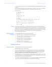
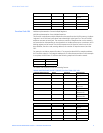
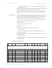
Data Packet Format A complete request/response sequence consists of the following bytes (transmitted as
separate data frames):
Master Request Transmission:
SLAVE ADDRESS: 1 byte
FUNCTION CODE: 1 byte
DATA: variable number of bytes depending on FUNCTION CODE