


COMMUNICATIONS GUIDE RS485 INTERFACE (MODBUS RTU)
MM200 MOTOR MANAGEMENT SYSTEM – COMMUNICATIONS GUIDE 5
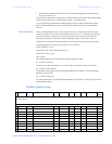
The master/slave packets have the following format:
Table 1: MASTER/SLAVE PACKET FORMAT FOR FUNCTION CODE 03H
Function Code 04H Modbus Implementation: Read Input Registers
MM200 implementation: Read Actual Values
For the MM200 implementation of Modbus, this function code can be used to read any
actual values (“input registers”). Input registers are 16 bit (two byte) values transmitted high
order byte first. Thus all MM200 Actual Values are sent as two bytes. The maximum
number of registers that can be read in one transmission is 125.
The slave response to this function code is the slave address, function code, a count of the
data bytes to follow, the data itself and the CRC. Each data item is sent as a two byte
number with the high order byte sent first.
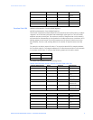
For example, request slave 17 to respond with 1 register starting at address 0008. For this
example the value in this register (0008) is 0000.
Address Data
006B 022B
006C 0000
006D 0064
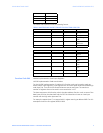
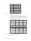
MASTER TRANSMISSION BYTES EXAMPLE DESCRIPTION
SLAVE ADDRESS 1 11 message for slave
17
FUNCTION CODE 1 03 read registers
DATA STARTING ADDRESS 2 00 6B data starting at
006B
NUMBER OF SETPOINTS 2 00 03 3 registers = 6
bytes total
CRC 2 76 87 CRC error code
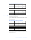
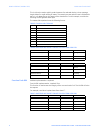
SLAVE RESPONSE BYTES EXAMPLE DESCRIPTION
SLAVE ADDRESS 1 11 message from
slave 17
FUNCTION CODE 1 03 read registers
BYTE COUNT 1 06 3 registers = 6
bytes
DATA 1 (see definition above) 2 02 2B value in address
006B
DATA 2 (see definition above) 2 00 00 value in address
006C
DATA 3 (see definition above) 2 00 64 value in address
006D
CRC 2 54 83 CRC error code