


28 MM200 MOTOR MANAGEMENT SYSTEM – COMMUNICATIONS GUIDE
FIELDBUS INTERFACE COMMUNICATIONS GUIDE
Fieldbus interface
The fieldbus interface is configurable as either Profibus DPV0 or DeviceNet. Both Fieldbus
interfaces support control and status – refer to the specific data map below for details.
Note that external power, 5 to 24 VDC, is required for this interface to operate. (Ensure that
switches 7 and 8 of the DIPswitch on the communication card, are ON.)
Profibus protocol (DP V0)
To enable the Profibus physical interface, ensure that switches 3 and 4 of the DIP switch on
the communications card (on the CPU) are on. The external connections through the
Fieldbus interface are as follows.
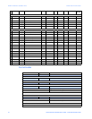
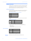
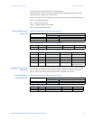
Table 10: Fieldbus interface external connections (Profibus)
The Modbus status (MS) and network status (NS) LEDs indicate the status of the Fieldbus
interface.
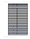
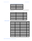
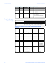
Table 11: Profibus LED indications
When used for Profibus, the fieldbus port has the following characteristics.
• Baud rate: 9600, 19200, 31250, 45450, 93750, 187500, 500000, and 1.5M bps
• Address: 1 to 125
• Vendor ID: 3005 (hex)
• Data table size: inputs = 240 bytes, outputs = 240 bytes
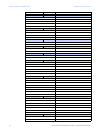
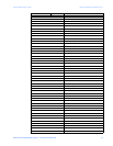
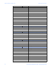
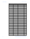
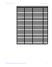
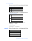
Profibus Output Data
Commands are actioned on rising edge (0 to 1 transition).
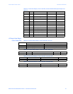
Profibus DP-
Diagnostics
MM200 supports bot slave mandatory and slave specific diagnostic data.
Pin Connection (external device)
V– Pin 5
L Pin 8, line A (negative TX/RX)
CCommon drain
H Pin 3, line B (positive TX/RX)
V+ Pin 6
LED Color Description
MS Green Processor OK
Off Processor FAIL
NS Green Communications to master OK
Red Communications to master FAIL
Bit Description
0Reset
1Lockout Reset
2Stop
3Start A
4Start B