


COMMUNICATIONS GUIDE FIELDBUS INTERFACE
MM200 MOTOR MANAGEMENT SYSTEM – COMMUNICATIONS GUIDE 29
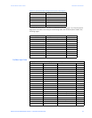
Table 12: System Standard Diagnostics Bytes 1 through 6
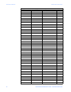
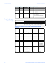
The extended diagnosis for the relay is composed of 49 bytes (bytes 7 to 55) and contains
diagnostic information according to the following table, with bit descriptions listed in the
following pages.
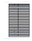
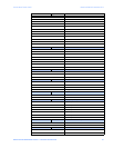
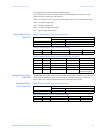
Profibus Input Data
Byte Description
0 Station Status 1
1 Station Status 2
2 Station Status 3
3 Diagnostic Master Address
4 Identification Number (High Byte)
5 Identification Number (Low Byte)
Address (By Bytes) Description Format
6 No. of Extended Diagnostic Bytes Unsigned
7-10 Reserved
11-14 Trip Status 2 FC184
15-18 Trip Status 1 FC183
19-22 Reserved
23-26 Alarm Status 2 FC180
27-30 Alarm Status 1 FC179
31-46 Reserved
47-50 Ctrl Element Status 2 FC192
51-54 Ctrl Element Status 1 FC191
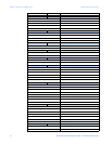
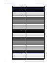
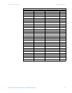
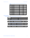
Category Address (By Bytes) Description Format
Status-Motor 0 Motor Status FC129
2 Extended Status FC178
4 Thermal Cap Used F1
6 Time to Overload Trip F20
10 Overload Lockout F1
12 Reserved NA
14 Reserved NA
16 Reserved F1
18 Reserved NA
20 Reserved NA
22 Reserved NA
24 Reserved NA
26 Reserved NA
Learned 28 Learned Acceleration Time F2
30 Learned Starting Current F10
34 Learned Starting Capacity F1
Counters 36 Number of Motor Starts F1
38 Reserved NA
40 Motor Running Hours F9
44 Reserved NA
46 Reserved NA