


32 MM200 MOTOR MANAGEMENT SYSTEM – COMMUNICATIONS GUIDE
FIELDBUS INTERFACE COMMUNICATIONS GUIDE
DeviceNet protocol
To enable the DeviceNet physical interface, ensure that switches 1 and 2 of the DIP switch
communications card (on the CPU) are on. The external connections through the fieldbus
interface are as follows.
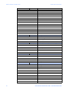
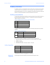
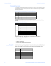
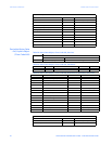
Table 13: Fieldbus interface external connections (DeviceNet)
The Modbus status (MS) and network status (NS) LEDs indicate the status of the Fieldbus
interface.
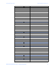
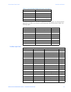
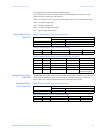
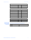
Table 14: DeviceNet LED indications
When used for DeviceNet, the fieldbus port has the following characteristics.
• Baud rate: 125, 250, and 500 kbps
• MAC ID: 0 to 63
•Vendor ID: 928
• Product Code: 0x4D39
• Message types: poll, and explicit messaging
DeviceNet
Communications
The device profile is an extension of the Communications Adapter Device Profile (0xC0). It is
a group 2 only server. The MAC ID and baud rate are programmable through the EnerVista
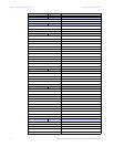
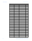
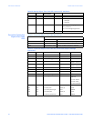
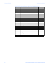
MM200 Setup software. The MM200 supports the following DeviceNet object classes.
Path Connection (external) Wire color
V– Pin 3, CAN_GND Black
L Pin 2, CAN_L Blue
C Pin 5, CAN_SHLD Bare
H Pin 7, CAN_H White
V+ Pin 9, CAN_V Red
LED LED operation Description
MS Green on, red on, green on Device self-test
Flashing green Device in standby state
Green on Device operational
Flashing red Recoverable fault
Red on Unrecoverable fault
NS Flashing green Online, not connected
Green on Online, connected
Flashing red Connection timeout
Red on Critical link failure
Red and green Network access detected
CLASS OBJECT
01H Identify
02H Message Router
03H DeviceNet
05H Connection
64H IO Data
A0H Generic Data - Polling/Explicit
B1H Explicit Control Writes
B0H Analog Data - Explicit