145
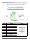
A.5 Attach the external output module
The output module provides two outputs, 0–20 mA/4–20 mA, 500 Ohm.
1. Remove power and disconnect all cable connections to the module.
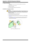
2. Place the External Output Module on the DIN rail to the right of the base module and
slide firmly against the base module (or other connected modules).
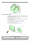
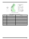
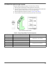
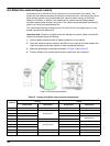
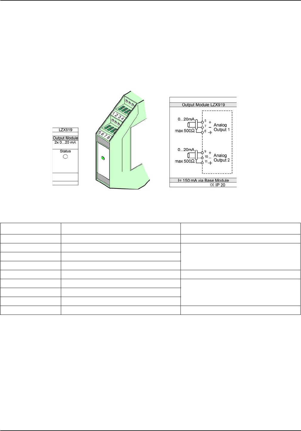
3. Make the appropriate connections as shown in Figure 78 and Table 51.
4. Connect cables to the module and reconnect power from the instrument.
Figure 78 External output module
Table 51 External Output Module Terminal Assignments
Terminal Assignment Description
1–4 Not used —
5–
Analog output 1 max. 500 Ohm6Shield
7+
8 Not used —
9–
Analog output 2 max 500 Ohm10 +
11 Shield
12–16 Not used —


