


20
Installation
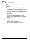
3.4.3 Wiring for AC power at the controller
DANGER
Electrocution hazard. Failure to connect to a good low impedance Protective Earth
ground can result in both a shock hazard and poor performance against
electro-magnetic interferences.
1. Obtain appropriate fittings with IP65 environmental rating.
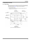
2. Remove the display module from the probe module (Figure 5).
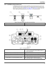
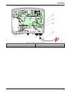
3. Remove the four screws securing the probe module front cover. Open the probe
module and disconnect the chassis ground connection from the ground stud to the
cover.
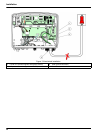
4. Remove the six screws from the high voltage barrier and remove the barrier.
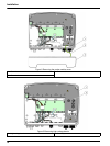
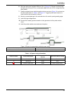
5. Insert the wires through the PG1 opening and strain relief fitting or conduit hub.
Tighten the strain relief if used, to secure the cord.
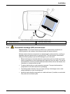
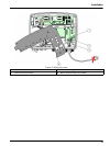
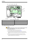
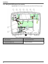
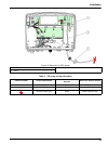
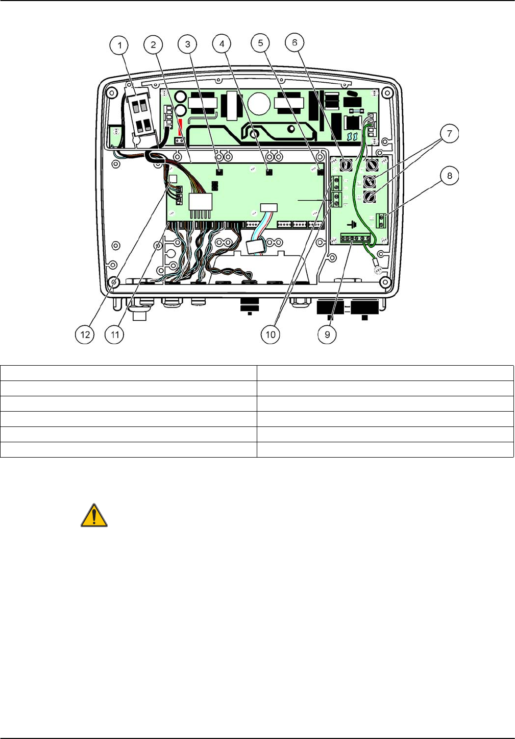
Figure 11 Inside the AC probe module
1 Fan 7 Fuse (2x), F3 and F4: T 8A; 100–240 V, slow-blow
2 Main circuit board 8 AC power connections
3 Connector for expansion slot 9 Earth ground connection
4 Connector for expansion slot 10 Power outlet connection
5 Connector for expansion slot 11 Probe connections
6 Fuse (2x), F1 and F2: M 3.5A, medium blow 12 Relay card connection