16
Installation
3.4 Electrical installation
DANGER
Electrocution hazard. Only qualified personnel should conduct the installation
tasks described in this section of the manual.
DANGER
Electrocution hazard. Always install a ground fault interrupt circuit (GFIC)/ residual
current circuit breaker (rccb) with a maximum trigger current of 30 mA. If installed
outside, provide overvoltage protection.
If installed outdoors, provide overvoltage protection between the power and the sc1000
controller. Make sure the data and power cables do not cause tripping and do not contain
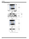
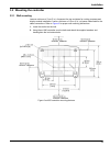
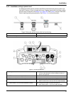
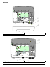
any sharp bends. Refer to Figure 7 for housing breakout information.
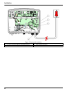
High-voltage wiring for the controller is conducted behind the high voltage barrier in the
controller enclosure. The barrier must remain in place unless a qualified installation
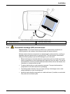
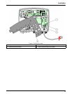
technician is installing wiring for power, alarms, or relays. See Figure 9 for barrier
removal information.
The instrument can be wired for line power by hard-wiring in conduit or by wiring to a
power cord if allowed by local electrical code. A local disconnect designed to meet local
electrical code is required and must be identified for all types of installation.
Do not connect the electrical power supply to the AC power until the sc1000 controller
has been fully wired, fused, and the high voltage barrier and probe module cover have
been replaced.
3.4.1 Installation in hard-wired applications
In hard-wired electrical applications, the power and safety ground service drops for the
instrument must be 18 to 12 AWG. A sealing-type strain relief must be used to maintain
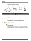
the IP65 environmental rating. See Figure 6 for strain relief and conduit opening sealing
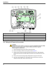
plug assembly. See Figure 13 for wiring information.
Note: There is no on/off switch to disconnect the probe module from AC Power.


