


146
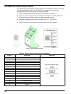
A.6 Attach the external input module
Instruments with (0–20 mA/4–20 mA) outputs can be connected to this module. The
signals can be scaled as required and be given names and units. Instruments that do not
have network options can be connected to the network system using a sc1000 with
Modbus or Profibus. In addition, this module can be used to monitor floating digital
switches (external relay contacts as inputs). The module cannot be used to provide 24V
power to a 2-wire (loop-powered) device.
This module provides two analog inputs (0–20 mA/4–20 mA), two digital inputs, or one
analog input and one digital input.
Important Note: Potential on digital inputs can damage the system. Make sure that the
signals on the digital inputs are floating.
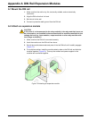
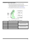
1. Remove power and disconnect all cable connections to the module.
2. Place the external output module on the DIN rail to the right of the base module and
slide firmly against the base module (or other connected modules).
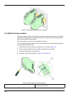
3. Make the appropriate connections as shown in Figure 79 and Table 52.
4. Connect cables to the module and reconnect power from the instrument.
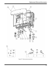
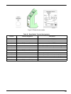
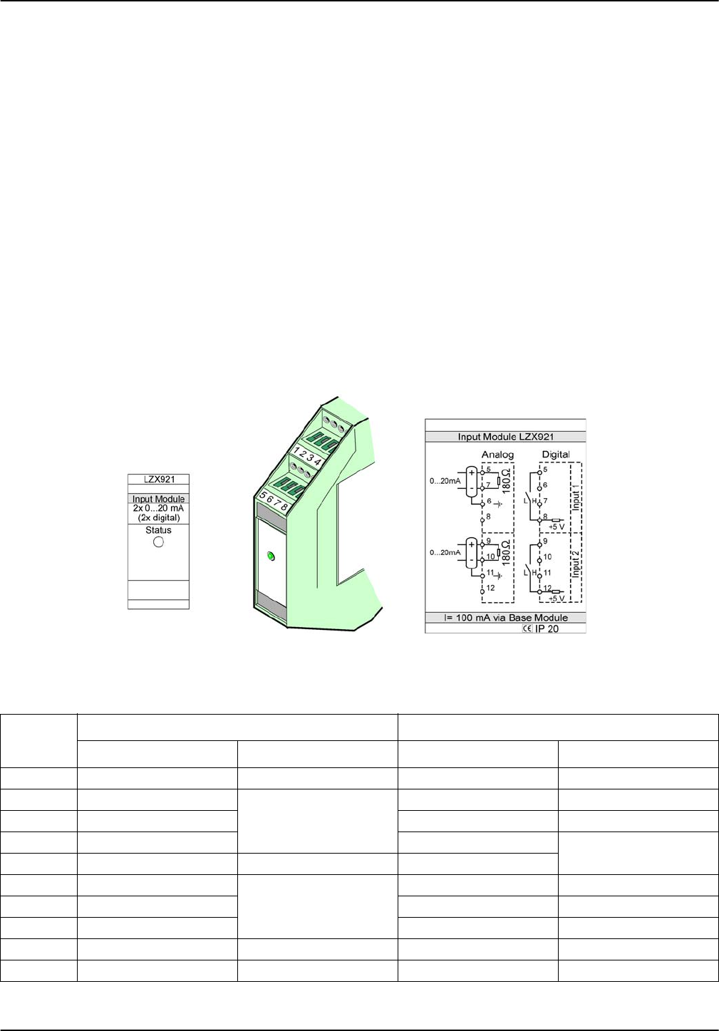
Figure 79 External input module
Table 52 Analog and digital output terminal assignments
Terminal
Analog Digital
Assignment Description Assignment Description
1–4 Not used — Not used —
5 Input –
Analog Input 1
Not used —
6 Shield Not used —
7 Input + Contact 1
Digital Input 1
8 Not used — Contact 2
9 Input –
Analog Input 2
Not used —
10 Input + Contact 1 Digital Input 2
11 Shield Not used —
12 Not used — Contact 2 Digital Input 2
13–16 Not used — Not used —