


1-5
Introducing the Switch
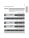
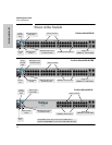
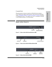
Front of the Switch
Introducing the Switch
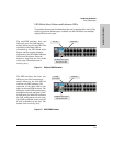
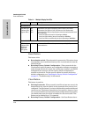
Network Ports
■ 24, or 48 auto-sensing 10/100Base-TX ports.
All these ports have the “Auto-MDIX” feature, which means that you can
use either straight-through or crossover twisted-pair cables to connect
any network devices to the switch.
■ Two RJ-45 10/100/1000Base-T ports for high speed uplink.
■ Two mini-GBIC (SPF) slots for fiber uplinks.
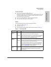
LEDs
On the 2610 Switches, there are three groupings of LEDs:
■ switch status LEDs (Table 1-2)
■ port LEDs (Table 1-3)
■ Port LED Mode indicator LEDs (near the selector button) (Table 1-4)
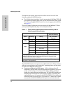
Table 1-2. Switch Status LEDs
Switch LEDs State Meaning
Power
(green)
On The internal power supply is working properly.
Off No power connection. The switch is NOT receiving power.
Flashing
2
A failure of the internal power supply. It should be flashing simultaneously
with the Fault LED. (If an RPS is connected to the switch, the RPS is
actively powering the switch, the RPS LED will be on.)
Fault
(orange)
Off The normal state; indicates there are no fault conditions on the switch.
Flashing
2
A fault has occurred with a component on the switch. The Status LED for
the component with the fault will flash simultaneously.
On On briefly after the switch is powered on or reset, at the beginning of
switch self test. If this LED is on for a prolonged time, the switch has
encountered a fatal hardware failure, or has failed its self test. See
chapter 4, “Troubleshooting” for more information.
Locator
(blue)
On
Flashing
Off
The Locator LED is used to locate a specific switch in an area full of
switches. The LED can be set to be on solid or flash for a specified number
of minutes (1-1440). The default is 30 minutes. Use the command
“chassislocate”.