


2-24
Installing the Switch
Installation Procedures
Installing the Switch
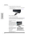
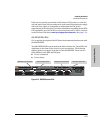
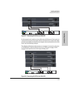
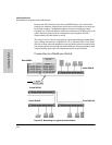
The following illustration demonstrates an example of connectivity between
an RPS/EPS device and a Switch device as a PoE power supply.
Figure 2-15. Connecting a 600 RPS/EPS to a 2610 EPS
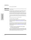
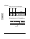
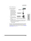
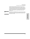
610 EPS LEDs
Figure 2-16. EPS status LEDs
For a complete description of the LEDs see the documentation that came with
the 610 EPS.
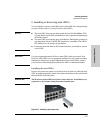
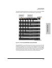
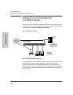
For redundant or additional PoE power, connect the 610 EPS to the switch
using one of the four supplied EPS cables. EPS cables are 2.00 meters (6.56
feet) in length.
The following illustration demonstrates an example of connectivity between
a 610 EPS device and two Switch devices as a PoE power supply.
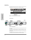
Switch EPS output
EPS input port
Power
Fault
hpprocurve
610
eps
J8169A
Fan/Temp Status flash = Temperature too high
Fan/Temp Status + Fault flash = Fan failure
Fan/Temp Status
Internal Power Status
In Ready
Out Ready
Backup Power Ports Status
EPS Ports PairA
(
408 W total for PoE applications
)
EPS Ports:50V 8.3A maxeach.
EPS A1
Power
Status
A2
B1
B2
A1
Device
Connected
EPS A2 EPS B1
Power
Status
Device
Connected
EPS B2
EPS Ports PairB
(
408 W total for PoE applications
)
Power and
Fault LEDs
610 EPS
Internal Power
Status LED
Fan/Temp
Status LED
Backup Power
Port LEDs
EPS Port LEDs
Device Connected
LED
Power Status
LED