


2-19
Installing the Switch
Installation Procedures
Installing the Switch
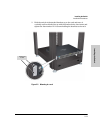
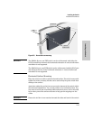
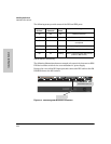
The 600 RPS/EPS provides two types of power to the
switches:
■ Redundant power to one of up to six switches, to back up the internal
switch power supply in case of AC power loss, or a fault condition. Should
the internal switch power supply fail, power will be supplied from the 600
RPS/EPS, if it is available, that is, if the 600 RPS/EPS is not already
providing power to a higher priority switch. See the documentation that
came with your 600 RPS/EPS for more information.
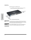
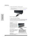
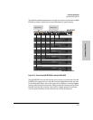
■ External Power-over-Ethernet (PoE) power to up to two switch products.
The 600 RPS/EPS can supply 408 watts of PoE power to the switch if the
internal PoE power supply should fail. For the Switch 2610-24/12PWR and
2610-48-PWR the external PoE power is additional power made available
to the switch’s ports. For further information regarding the 600 RPS/EPS
PoE capabilities, see the PoE Planning and Implementation Guide and
the ProCurve 600/610 External Power Supplies Installation and Getting
Started Guide, which is on the ProCurve Web site at www.hp.com/go/
procurve/manuals, (See page 1-13).
The 600 RPS/EPS is an unmanaged power supply that only provides
information by way of LEDs.
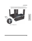
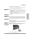
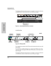
The 610 EPS only provides external PoE power:
■ External Power-over-Ethernet (PoE) power to up to four switch products.
The 610 EPS can supply 408 watts (if one port of a pair is used) or 204
watts (if two ports of a pair are used) of PoE power to the switch if the
internal PoE power supply should fail. For the Switch 2610-48-PWR the
external PoE power is additional power made available to the switch’s
ports. For further information regarding the 600 RPS/EPS and the 610 EPS
PoE capabilities, see the PoE Planning and Implementation Guide and
the ProCurve 600/610 External Power Supplies Installation and Getting
Started Guide, which is on the ProCurve Web site at www.hp.com/go/
procurve/manuals, (See page 1-13).
The 610 EPS is an unmanaged power supply that only provides informa-
tion by way of LEDs.
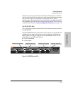
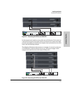
RPS/EPS Operation
The RPS/EPS monitors the power signal from the switch by detecting that the
RPS/EPS is connected to a switch with an RPS/EPS cable. When the power
from the switch is no longer detected, the RPS/EPS will provide power to the
switch within 1 millisecond.