


1-9
Introducing the Switch
Front of the Switch
Introducing the Switch
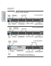
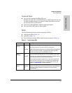
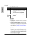
LED Mode Select Button and Indicator LEDs
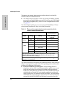
To optimize the amount of information that can be displayed for each of the
switch ports in the limited space available, the 2610 Switches use multiple-
display LEDs for each port.
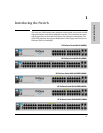
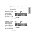
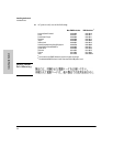
Figure 1-1. 2610 non-PWR Switches
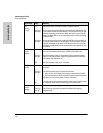
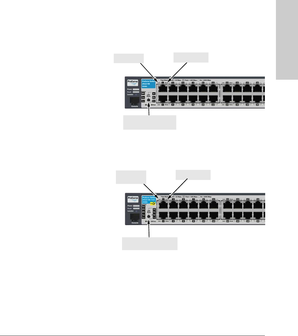
Figure 1-2. 2610-PWR Switches
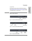
Mode LED
Link LED
LED Mode select button
and indicator LEDs
The non-PWR switches, have two
LEDs per port. The Link status is
always shown by the Link LED. The
operation of the Mode LED is
controlled by the LED Mode select
button, and the current setting is
indicated by the LED Mode indicator
LEDs near the button. Press the
button to step from one view mode
to the next. The default view is
Activity (Act).
Mode LED
Link LED
(port number)
LED Mode select button
and indicator LEDs
The PWR switches also have two
LEDs per port. The Link status is
always shown by the Link LED as
with the non-PWR switches. The
operation of the Mode LED is the
same as the non-PWR switches. The
difference is the PWR switches have
an additional mode, and that is PoE.
In PoE mode, the Link LED indicates
the PoE configuration for the port:
On if PoE is enabled on the port; Off
if PoE is disabled on the port. The
default view is Activity (Act).