


2-22
Installing the Switch
Installation Procedures
Installing the Switch
The following states provide status of the RPS and EPS ports.
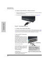
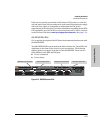
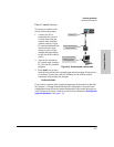
600 RPS/EPS Connectivity
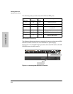
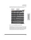
The following illustration shows an example of connectivity between an RPS/
EPS device and a switch device as a redundant AC power supply.
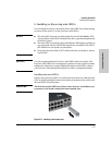
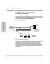
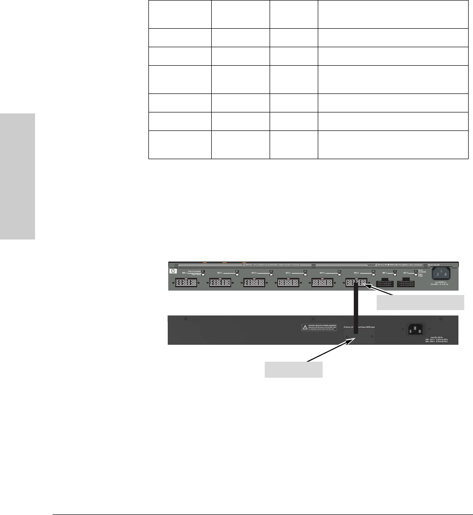
Remove the cover of the RPS input port and connect the RPS cable to the 600
RPS/EPS then to the 2610 switch.
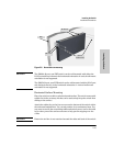
Figure 2-13. Connecting a 600 RPS/EPS to a 2610 RPS
Fault (located on
the front)
Device
Connected
Power
Status
Message
Off Off Off Nothing Connected
On or Off Off On Not a valid state - should never happen
Off On Off Switch is connected, RPS is available but
not required
Off On On RPS is powering the connected device
Flashing Off Flashing RPS/EPS port is in fault condition
Off On Flashing Switch is requesting power, RPS can not
provide it. (N/A for EPS)
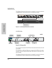
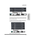
RPS input port
Switch RPS output port