


2-32
Installing the Switch
Sample Network Topologies for PWR Switches
Installing the Switch
Sample Network Topologies for PWR
Switches
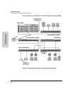
This section shows a few sample network topologies for implementing the
Switch 2610-PWR Series. For more topology information, see the ProCurve
networking products Web site, www.hp.com/go/procurve/manuals.
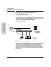
As a Desktop Switch Implementing PoE
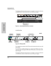
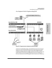
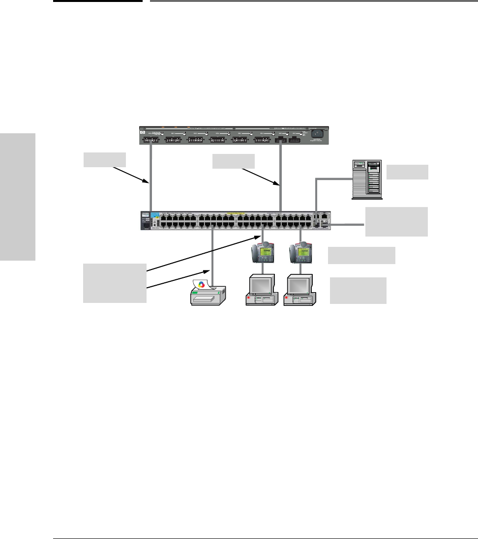
Figure 2-23. Basic desktop configuration with external power
The Switch 2610-PWR Series are also designed to be used as desktop switches
to which end nodes, printers and other peripherals, and servers are directly
connected, as shown in the above illustration. Except now these switches can
supply PoE power to end devices such as IP telephones.
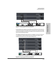
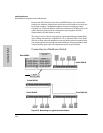
As shown in the above illustration the IP telephones can be connected in line,
that is, between the switch and the end device, in this case a PC. The IP
telephones have two ports, one in and one out. Therefore the phone receives
voice and power from the switch and the PC can send and receive data through
the phone to the switch.
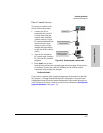
The end node devices are connected to the switch by straight-through or
crossover twisted-pair cables. Either cable type can be used because of the
Auto-MDIX feature on the Switch 2610-PWR Series.
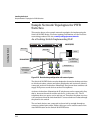
Server
2610-48-PWR
PCs and
peripherals
IP Telephones
600 RPS/EPS
Gigabit
fiber-optic cable
to backbone
RPS cable
EPS cable
Twisted-pair
straight-through
or crossover
cables