


Troubleshooting Analysis Guide (TAGs) 3-57
16
Clean both the photoconductor LED and seam sensor using a cotton swab or compressed air.
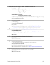
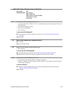
• Run diagnostic 009.
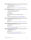
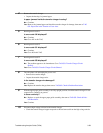
• Using an oscilloscope connected to TP3-20 on the PCL board, adjust the signal so that it
matches figure A by moving the sensor bracket closer or farther from the photoconductor unit.
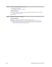
Figure B illustrates a bad signal. Note that 7ms is the recommended minimum length of time the
waveform should maintain 0v; you may have to settle for less. The two small signals prior to the
12v signal are from the smaller holes in the photoconductor unit; the larger signal is from the
cutout for the PC sensor.
Is the signal adjusted to match that illustrated in Figure A?
No: Repeat this step until the signal has been adjusted properly.
Yes: Turn to TAG 002: Check & Problem Resolution.
Figure A Figure B
12V
0V
7 ms
12V
0V