


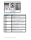
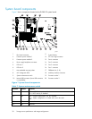
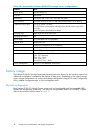

Table 8 In terpreting the drive status LEDs
Online LED
(green)
Fault/ID LED
(amber/blue)
Meaning
On, off, or flashing
Alternating be
tween
amber and blue
The drive has failed, or a predictive failure alert* has
been received for this drive. It has also been selected by
a management application.
On, off, or flashing
Steadily blue The drive is operating normally, and it has been selected by
a management application.
On
Amber, flashing
regularly (1 Hz)
A predictive failure alert* has been received for this drive.
Replace the drive as soon as possible.
On
Off
The drive is online, but it is not currently active.
Flashing regularly
(1 Hz)
Amber, flashing
regularly (1 Hz)
The drive is part of an array that is undergoing capacity
expansion or stripe migration, but a predictive failure alert*
has been received for this drive. To minimize the risk of
data loss, do not replace the drive until the expansion or
migration is complete.
Flashing regularly
(1 Hz)
Off The drive is rebuilding, or it is part of an array that is
undergoing capacit y expansion or stripe migration.
Flashing irregularly
Amber, flas
hing
regularly
(1 Hz)
The drive i
s active, but a predictive failure alert* has been
received f
or this drive. Replace the drive as soon as possible.
Flashing irregularly
Off
The drive is active, and it is operating n ormally.
Off
Steadily amber
A critical fault cond ition has been identified for this drive,
and the controller has placed it offline. Replace the drive
as soon as possible.
Off Amber, fla
shing
regularl
y(1Hz)
Apredict
ive failure alert* has been received for this drive.
Replace t
he drive as soon as possible.
Off Off The drive is either offline, a spare, or not configured as part
of an array.
* Predictive failure alerts can occur only when the MSA20 is connected to a Smart Array controller .
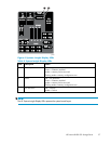
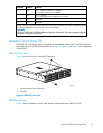
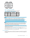
Modular Smart Array 30
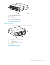
TheDL380G51.2TBStorageServerisprovidedwithoneModularSmartArray30(MSA30)enclosure
populated with four 300–GB SCSI hard disk drives. Figure 11, Figure 12, Figure 13,andFigure 14
show components of the MSA30.
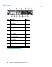
Modular Smart Array 30 front view
Figure 11 shows a front view of the Modular Sm a rt Array (MSA) 30 enclosure.
34
Storage server specifications and image configurations