


To use a timing analyzer to detect a glitch
The following setup uses a state analyzer to capture state flow occurring at
the time of the glitch. This can be useful in troubleshooting. For example, you
might find that the glitch is ground bounce caused by a number of
simultaneous signal transitions.
1
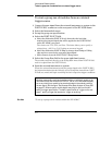
Select the Intermodule menu.
2 Select the timing analyzer from the Modules list and set it to Group
Run. Select the state analyzer and set it to respond to the arm signal
from the timing analyzer.
You must have fully independent state and timing analyzers to make this type
of measurement. For example, though the HP 16550A can be configured to
use some of its channels for a state analyzer and some for a timing analyzer, it
cannot present those analyzers independently for intermodule measurements.
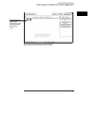
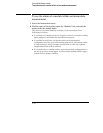
3
Select the timing analyzer Trigger menu.
4 Select an Edge term. Then assign glitch detection “*” to the channels
of interest represented by the Edge term.
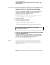
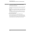
5 Select the state analyzer Trigger menu.
6 Set the analyzer to trigger on any state and store any state.
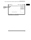
7 Select Group Run in the upper right corner of the display.
If you don’t see the activity of interest in the state trace, try changing the
trigger position using the Acquisition Control field in the Trigger menu of the
state analyzer. By changing the Acquisition mode to manual, you can position
the trigger at any state relative to analyzer memory.
The timing analyzer can detect glitch activity on a waveform. A glitch is defined
as two or more transitions across the logic threshold between adjacent timing
analyzer samples.
Intermodule Measurements
To use a timing analyzer to detect a glitch
2–14