


To adjust for minimum skew between two modules
involved in an intermodule measurement
1 Connect an input signal from each module to the same signal.
An ideal signal for testing skew is a single-shot signal with fast risetime. Such
a signal simplifies triggering and makes it easier to correlate the input event
between the modules. Ensure that you use proper probe grounding for
maximum signal fidelity.
2
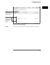
Select the Intermodule menu.
3 Set up both modules so they will begin searching for the trigger
immediately when a group run begins.
This setup focuses mostly on trying to eliminate probe skew and internal
triggering delays. You can use other intermodule setups as well. For example,
you may be interested in nullifying the effects of the internal arming delay in
a setup where one module arms another.
4
Set up the trigger conditions for each module.
This will depend upon your input signal. For example, if you are adjusting
intermodule skew using a single-shot pulse with a rising edge, set a timing
analyzer to trigger on a rising edge using the Edge1 term, and the
oscilloscope to trigger on a positive slope.
5
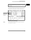
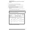
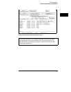
Select the Display or Waveform menu in one of the modules.
6 Set up the display so that both input waveforms are displayed
simultaneously.
You do this by selecting the label field to the left of the display twice. The
second selection brings up a new menu that allows you to insert or delete
waveforms. You can delete all but the waveform of interest from the first
module, then add the waveform of interest from the second module. Select
Done when finished.
7
Select Group Run.
You may now need to trigger the signal of interest, if, for example, it is
activated by a push button. You may need multiple events to capture good
waveforms for both measurement modules. Remember that the oscilloscope
captures far more accurate waveform data than the timing analyzer. Thus, if
the waveforms do not match exactly, it may only be because the waveform
edge did not meet the timing analyzer’s setup and hold time specifications for
a particular sampling period.
Intermodule Measurements
To adjust for minimum skew between two modules involved in an intermodule measurement
2–27