


The Inverse Assembler
When the analyzer captures a trace, it captures binary information.
The analyzer can then present this information in binary, octal,
decimal, hexadecimal, or ASCII. Or, if given information about the
meaning of the data captured, the analyzer can inverse assemble the
trace. The inverse assembler makes the trace list more readable by
presenting the trace results in terms of processor opcodes and data
transactions.
The inverse assembly software needs five pieces of information:
• Address bus. The inverse assembler expects to see the label ADDR,
with bits ordered in a particular sequence.
• Data bus. The inverse assembler expects to see the label DATA,
with bits ordered in a particular sequence.
• Status. The inverse assembler expects to see the label STAT, with
bits ordered in a particular sequence.
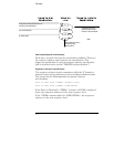
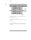
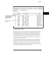
• Start state for disassembly. This is the first displayed state in the
trace list, not the cursor position. See the figure below.
• Tables indicating the meaning of particular status and data
combinations.
When you press the Invasm key to begin inverse assembly of a trace,
the inverse assembler begins with the first displayed state in the trace
list. This is called synchronization. It looks at the status bits (STAT)
and determines the type of processor operation, which is then
displayed under the STAT label. If the operation is an opcode fetch,
the inverse assembler uses the information on the data bus to look up
the corresponding opcode in a table, which is displayed under the
DATA label. If the operation is a data transfer, the data and
corresponding operation are displayed under the DATA label. This
continues for all subsequent states in the trace list.
4–10