


To test a circuit using stimulus-response
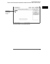
1 Select the Intermodule menu.
2 Select the pattern generator from the Modules list and set it to Group
Run. Select the oscilloscope module and set it to respond to the arm
signal from the pattern generator. Select the state analyzer and set it
to respond to the arm signal from the pattern generator.
3 Load the pattern generator with the proper patterns to simulate the
signals from the driving hardware.
4 Insert the “Signal IMB” instruction at the desired point in the pattern
generator program.
The arm signal is programmable. It can occur anywhere in the pattern
generator cycle.
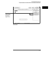
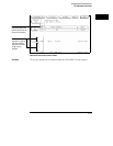
5
Select the oscilloscope Trigger Menu. Set the oscilloscope to trigger
on signals of interest in the circuit under test.
6 Select the state analyzer Trigger Menu. Set the analyzer to trigger on
addresses, data, or status conditions of interest, and to store any
state or states of interest.
7 Select Group Run from the upper right corner of the display.
The pattern generator will begin its cycle, and will arm the oscilloscope and
state analyzer.
In the early stages of system design and integration, you may want to test a
circuit when the driving hardware that will stimulate it has not yet been
designed or fabricated. You can also use the pattern generators with the logic
analyzer to test PC boards when no board-test system is available.
The HP 16522A pattern generator for the HP 16500C avoids the inconvenience of
having to stack several signal generators on top of each other, with all of the
cable connections required for those signal generators. Additionally, you have a
single interface to access all the test modules in your measurement.
See Also The HP 16522A User’s Reference for the procedures for operating the
pattern generator.
Intermodule Measurements
To test a circuit using stimulus-response
2–17