


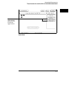

To capture the waveform of a glitch
The following setup uses the triggering capability of the timing analyzer and
the acquisition capability of the oscilloscope.
1
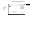
Select the Intermodule Menu.
2 Select the timing analyzer from the Modules list and set it to Group
Run. Select the oscilloscope module and set it to respond to the arm
signal from the timing analyzer.
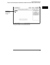
3 Select the timing analyzer module.
4 Select the Trigger menu, and within the menu, select an Edge term.
5 Assign glitch detection "*" to the channel of interest represented by
the Edge term.
This will usually be the same channel monitored by the oscilloscope.
6 Select the oscilloscope Trigger menu, and set Mode to Immediate.
7 Select the Group Run field in the upper right corner.
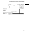
If you have trouble capturing the glitch waveform on the oscilloscope, try
adjusting the skew in the Intermodule menu, so the oscilloscope triggers
earlier.
A timing analyzer can trigger on a glitch and capture it, but a timing analyzer
doesn’t have the voltage or timing resolution to display the glitch in detail. An
oscilloscope can display a glitch waveform with fine resolution, but cannot
trigger on glitches, combinations of glitches, or sophisticated patterns involving
many channels.
Intermodule Measurements
To capture the waveform of a glitch
2–15