


Hardware options installation 58
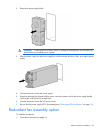
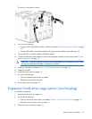
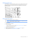
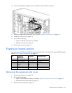
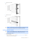
Identifying guide screws
When installing drives in the removable media bay, guide screws must be installed so that the drives align
correctly in the drive cage. HP has provided extra guide screws, located behind the side access panel.
Depending on the option, use 5.25 M3 metric screws or HD 6-32 shipping screws. The metric screws
supplied by HP are black.
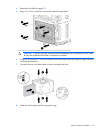
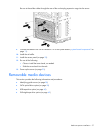
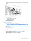
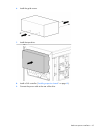
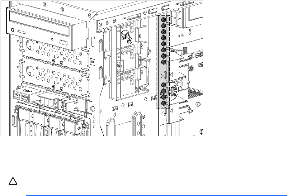
SATA optical drive option
For clarity, the following illustrations include option cabling only.
CAUTION: To prevent improper cooling and thermal damage, do not operate the server unless
all bays are populated with either a component or a blank.
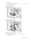
To install the component:
1. Power down the server (on page 20).
2. Do one of the following:
o Open or remove the tower bezel, as needed ("Open or remove the tower bezel" on page 20).
o Extend the server from the rack (on page 21).
3. Remove the access panel (on page 21).
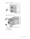
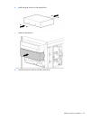
4. Remove the applicable media bay blank ("Remove the media bay blank" on page 23).
5. Identify the guide screws ("Identifying guide screws" on page 58).