


Service Manual Product Information 1-25
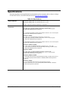
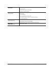
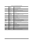
Table 1-8. Functional Structure Description
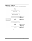
Bootup
CPU module
Motherboard
Hard disk drive
Floppy drive
Main processor (MMO)
Primary system circuitry, system BIOS
First source of disk-based startup code
Second source of disk-based startup cod.
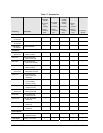
Processor
CPU module
Motherboard
Main processor, numeric data processor, L1 and L2 cache
Primary system circuitry
Memory
Motherboard
SDRAM module
Video RAM (XE4500)
Changeable SDRAM (2 slots), video RAM (XE4100)
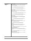
Power
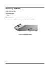
Battery
Motherboard
Switchboard PCA
AC adapter
Power storage
AC adapter socket, reset button, lid switch, power supply, power control circuitry
Power button
AC-to-DC converter
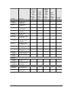
Display
Motherboard
SDRAM module
Display assembly
Graphics controller, video RAM
Display output, backlight, power converter for backlight
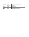
Hard disk
Motherboard
Hard disk drive
Hard disk controller
Hard disk mechanism
Floppy drive
Motherboard
Floppy drive
I/O controller, floppy connector
Floppy drive mechanism
Keyboard
Motherboard
Switchboard PCA
Keyboard
Keyboard BIOS, keyboard controller
Power switch, one-touch buttons
Key switches
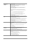
PS/2
TouchPad
Motherboard
Top case
Keyboard circuitry, keyboard controller, keyboard BIOS
Touch pad sensor, Select buttons, controller (PS/2 output)
Audio
Motherboard
Speaker assembly
Audio controller, audio decoder, speaker amplifier, microphone, external audio
jacks, headphone amplifier, audio-off switch
Speakers
Status
Motherboard
Switchboard PCA
Top case
LED circuitry, keyboard controller
Keyboard LEDs
Main status LEDs
Serial
Motherboard I/O controller, serial connector
Parallel
Motherboard I/O controller, parallel connector
Infrared
Motherboard
IR PCA
I/O controller
Infrared transmitter/receiver
PS/2 port
Motherboard PS/2 connector, keyboard controller
USB
Motherboard Bus controller (South Bridge), USB connector
S-Video
Motherboard I/O controller, S-video connector (certain models)