


iv Service Manual
Figures
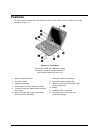
Figure 1-1. Front View................................................................................................................................ 1-8
Figure 1-2. Back View ................................................................................................................................ 1-9
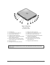
Figure 1-3. Bottom View........................................................................................................................... 1-10
Figure 1-4. Front View.............................................................................................................................. 1-11
Figure 1-5. Back View .............................................................................................................................. 1-12
Figure 1-6. Bottom View........................................................................................................................... 1-13
Figure 1-7. Resetting the Notebook .......................................................................................................... 1-17
Figure 1-8. Replaceable Module Diagram ................................................................................................ 1-24
Figure 2-1. Disassembly Flow..................................................................................................................... 2-3
Figure 2-2. Removing the Battery............................................................................................................... 2-4
Figure 2-3. Removing an SDRAM Module ................................................................................................ 2-5
Figure 2-4. Removing an SDRAM Module ................................................................................................ 2-6
Figure 2-5. Removing the Mini PCI Card................................................................................................... 2-7
Figure 2-6. Removing the Mini PCI Card................................................................................................... 2-8
Figure 2-7. Removing the Hard Disk Drive................................................................................................ 2-9
Figure 2-8. Removing the Hard Disk Drive Tray...................................................................................... 2-10
Figure 2-9. Removing the Keyboard Cover .............................................................................................. 2-14
Figure 2-10. Disconnecting the Speaker Cable......................................................................................... 2-14
Figure 2-11. Removing the Speaker Assembly......................................................................................... 2-15
Figure 2-12. Removing the Keyboard....................................................................................................... 2-17
Figure 2-13. Removing the Switchboard PCA.......................................................................................... 2-18
Figure 2-14. Removing the Switchboard PCA.......................................................................................... 2-19
Figure 2-15. Removing the CD/DVD Drive ............................................................................................. 2-21
Figure 2-16. Removing the CD/DVD Drive ............................................................................................. 2-22
Figure 2-17. Removing the Display Assembly ......................................................................................... 2-24
Figure 2-18. Removing the Top Case........................................................................................................ 2-27
Figure 2-19. Removing the Top Case Screws........................................................................................... 2-29
Figure 2-20. Removing the Top Case Screws........................................................................................... 2-30
Figure 2-21. Removing the Top Case........................................................................................................ 2-31
Figure 2-22. Removing the Floppy Drive ................................................................................................. 2-33
Figure 2-23. Removing the Floppy Drive ................................................................................................. 2-35
Figure 2-24. Removing the I/R PCA......................................................................................................... 2-37
Figure 2-25. Removing the Audio PCA.................................................................................................... 2-39
Figure 2-26. Removing the Heat Sink (with Fan)..................................................................................... 2-41
Figure 2-27. Removing the Heat Sink (with Fan)..................................................................................... 2-43
Figure 2-28. Removing the CPU Module.................................................................................................. 2-45
Figure 2-29. Removing the CPU Module.................................................................................................. 2-47
Figure 2-30. Removing the RJ11/1394 Connector Module ...................................................................... 2-49
Figure 2-31. Removing the Motherboard.................................................................................................. 2-51
Figure 2-32. Removing the Hard Disk Drive Guide .................................................................................2-53
Figure 2-33. Disconnecting the Motherboard Cables................................................................................ 2-54
Figure 2-34. Removing the Motherboard.................................................................................................. 2-56
Figure 2-35. Example of Serial Number Label ......................................................................................... 2-59
Figure 2-36. Replacing the Antennas........................................................................................................ 2-60
Figure 2-37. Removing a PCMCIA Door ................................................................................................. 2-60
Figure 2-38. Boot-Block Jumper............................................................................................................... 2-62
Figure 3-1. Basic Troubleshooting Steps .................................................................................................... 3-3
Figure 4-1. Exploded View ......................................................................................................................... 4-2
Figure 4-2. Exploded View ......................................................................................................................... 4-3