


CHAPTER 4 SETTING
9
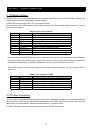
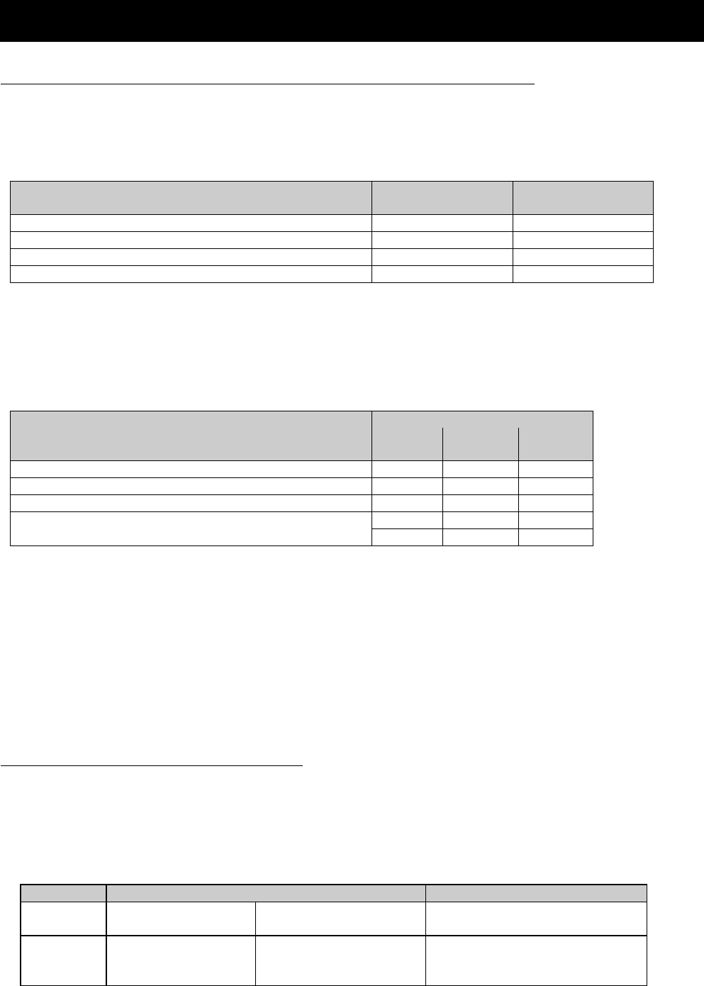
4.2 Setting of controlling frequency and start/stop commands
The SJ300/L300P inverters can be configured to take reference set-points and commands from several different
locations. Refer to the table below for information of how to configure the inverter so that the fieldbus controls
frequency and the commands.
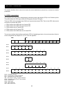
Control Frequency Setting
Selection - A001
Operation Setting
Selection - A002
SJ-PB(T) controls frequency and commands 2 1
SJ-PB(T) controls frequency only 2 Not equal to 1.
SJ-PB(T) controls commands only Not equal to 2. 1
SJ-PB(T) has no control. Not equal to 2. Not equal to 1.
However, since the SJ-PB(T) module uses the “Terminal” to give commands and “Operator” to give references to
the inverter certain steps must be taken in order to be able to control the inverter manually (not from fieldbus).
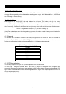
Study the table below to see how the control word bits shall be set to accomplish control from fieldbus and from
the user.
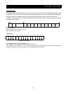
Control word bit settingsControlling the inverter with
A001 = 2 (Operator),
A002 = 1 (Terminal). 10 12 13
SJ-PB(T) controls frequency and commands 1 0 0
SJ-PB(T) controls frequency only* 1 1 0
SJ-PB(T) controls commands only 1 0 1
11 1
SJ-PB(T) has no control.
0- -
from the “Terminal” input when a SJ-PB(T) is present in the option slot. In order to do this, bit ten in the Control
Word shall be set to zero. That is, by setting A001=2, A002=1, and control word bit 10=0 it is possible to control
the inverter with the terminal while giving frequency reference from the fieldbus.
*Please note that when frequency reference is controlled from the fieldbus and commands from another location
(such as “Terminal”) the direction of the motor must be controlled from the command source (Reverse/Forward
command). In this case changing the sign of reference value cannot control the direction of the motor.
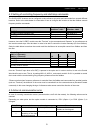
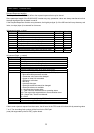
4.3 Action at communication error
In case of occurring transmission errors (communication cut-off with the master), the following actions can be
selected.
Depending on what option slot the option module is connected to, P001 (Option 1) or P002 (Option 2) is
changed.
P001/P002 Action at error detection Remarks
0 Inverter will trip. Option trip E6x or E7x. Fault can be reset either from
fieldbus or from keypad.
1
Continue operation
according to the last
received command.
--