


CHAPTER5 OPERATING
13
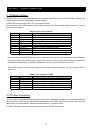
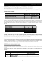
5.3 PZD-part
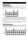
In this chapter the process data part (PZD) of a PPO is discussed.
The PZD part consists of a fixed part (PZD1-2, all PPO’s) and a parameterable part (PZD 3-10, shaded grey
above, PPO 2, 4 and 5).
In the fixed part, control word and speed reference are transferred to the inverter while status word and actual
output frequency are transferred from the inverter.
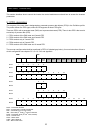
In the parameterable part, PZD word 3-10, the user can configure what parameters that should be transferred
to/from the inverter every bus-cycle (see chapter 5.3.3 and Appendix).
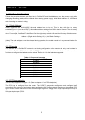
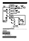
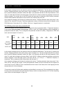
5.3.1 Control- / status word (STW/ZSW)
This section describes how to operate the inverter with the control-/status word. With the control word the
Profidrive state-machine (Figure 5-2) is controlled, the status word is reflecting the state of the inverter.
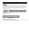
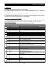
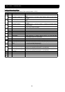
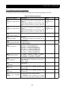
Profidrive Control Word (STW):
The control word is used to send control commands to the inverter (PLC->Inverter).
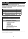
Control word
Bit Value Meaning Remark
1 On1 Inverter can be started if all other start conditions are fulfilled.0
0 OFF1 Normal stop; uses deceleration time specified in “1
st
Deceleration time” (F003).
1 ON2 Inverter can be started if all other start conditions are fulfilled.1
0 OFF2
Inverter coast to stop. Returns to Switch-on inhibit state.
1 ON3 Inverter can be started if all other start conditions are fulfilled.2
0 OFF 3 Quick stop that uses deceleration time specified in “2
nd
deceleration time”
(F203).
1 Operation enabled Inverter can be started if all other start conditions are fulfilled.3
0 Operation disabled
Inverter coast to stop (Enter Inhibit operation state).
1 Condition for operation Inverter can be started if all other start conditions are fulfilled.4
0 Ramp generator disabled Output frequency is set to zero. Inverter remains in the running state.
1 Ramp generator enabled Inverter can be started if all other start conditions are fulfilled.5
0 Stop ramp generator Actual output frequency is frozen. A change to frequency set-point has no
effect.
1 Enable set-point Inverter can be started if all other start conditions are fulfilled,
using “1
st
Acceleration time” (F002).
6
0 Inhibit set-point Normal stop that uses deceleration time specified in “1
st
deceleration time”.
1 Acknowledge Fault is acknowledged on positive edge, i.e. bit 7=0 then 1
(Enter Switch-on inhibited state).
7
0 No function
1 Inching 1 ON Inverter accelerates to inching set-point 1.
Profidrive must be in “Enable operation” state.
Parameter “Jogging frequency” specifies the jogging set-point (A038).
8
0 Inching 1 OFF
Inverter brakes as fast as possible and goes into the “Enable operation” state.
9 Not used
1 Data valid The control word and frequency set-point (from Profibus) are activated.
Please refer to chapter 2.2.4.
10
0 Data invalid The control word and frequency set-point (from Profibus) are not valid.
Please refer to chapter 2.2.4.
1 REV Inverter will operate in reverse motion.
Please note that a negative reference and reverse selected will result in inverter
running forward.
11
0 FWD Inverter will operate in forward motion.
1 Commands invalid The fieldbus module will not write any commands to the inverter. This makes it
possible to operate motor via the terminal input (if A002 is set to “Terminal”).
12
0 Commands valid The fieldbus module can write commands to the inverter (if A002 is set to
“Terminal”).
1 Reference invalid The fieldbus module will not write any reference to the inverter.13
0 Reference valid The fieldbus module can write reference to the inverter (if A001 is set to
“Operator”).
14,
15
Not used