


CHAPTER 6 COUNTERMEASURE FOR ABNORMALY
21
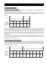
6.1 Trip display
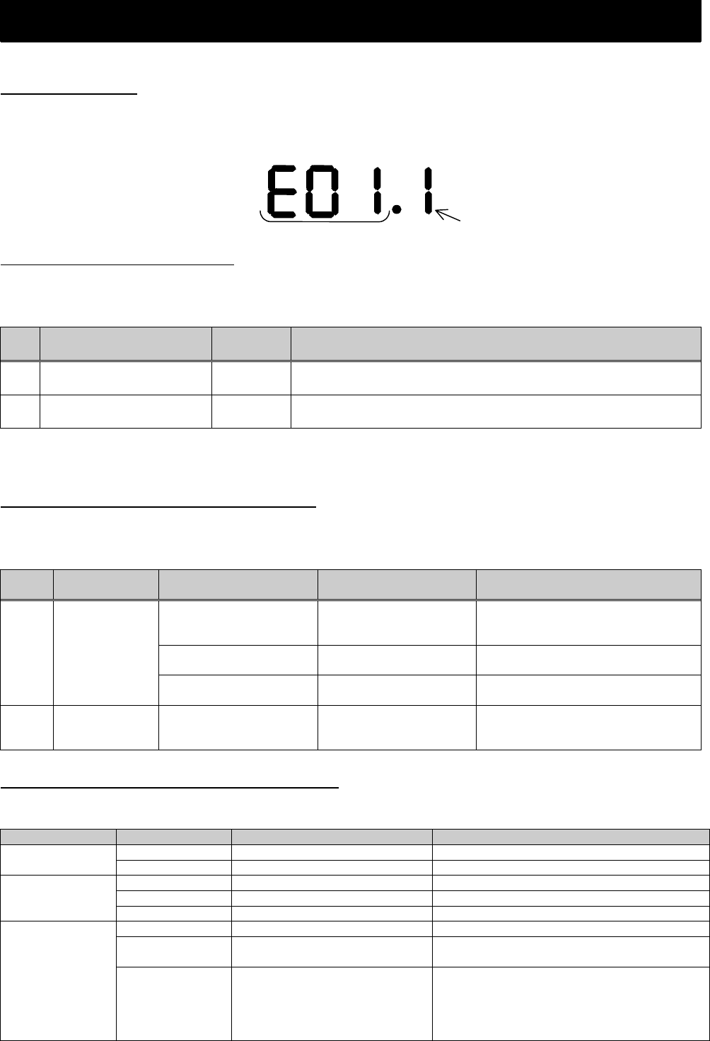
When the inverter is in a tripped state, the inverter displays an error code (See table below). The trip history
monitor (d081 to d086) also displays the same error code as the inverter.
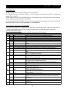
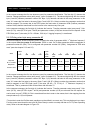
6.2 Protection function list
The table below describes an error code for protecting the inverter and the motor.
Error Display in the table below, X is 6 (Error for option slot 1) or 7 (Error for option slot 2).
No. Function Error
Display
Action
1 Profibus communication
error
EX0 This error is displayed, when disconnection occurred, while
the inverter is operating with Profibus.
2 Inverter communication
error
EX9 This error is displayed, when communication timeout occurs
between the inverter and the option board.
With regard to the other errors except table above, refer to Inverter instruction manual chapter 4 Explanation
of function.
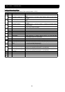
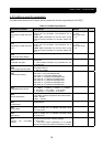
6.3 Countermeasure for a trip state
The table below only corresponds to additional trip codes, with regard to the other countermeasures refer to
Inverter instruction manual chapter 4 Explanation of function.
Trip
code
Name of trip Cause Conformation Countermeasure
Defective connector for
signal cable causes
connection fail.
Check the area of
connection.
Improve the connection and then
reset the power supply.
Terminating resistor is
not connected.
Check the Connection Connect the terminating Resistor
and then reset the power supply
EX0 Profibus
Communication
error
Wiring distance does not
much with baudrate.
Check the
wiring distance
Adjust the setting to the matching
Baudrate or adjust wiring distance
EX9 Inverter
communication
error
Option board is
removed.
Check as mentioned left Mount the option board again and
then secure it with screws.
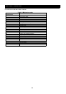
6.4 LED display and Countermeasure
Following states are indicated by three LED's.
LED Color Function Countermeasure
Green Fieldbus is on-line. -
Fieldbus
On/Off
Red Fieldbus is off-line. Confirm connection fails of connector.
Flash Red 1Hz Configuration error. Confirm setting data and send correct data.
Flash Red 2Hz User configuration data error. Confirm system setting and adjust adequate.
Fieldbus
diagnosis
Flash Red 4Hz VPC3+ initialization failed. Need to change the SJ-PB.
Green Serial channel status OK. -
Flash Red 1Hz Serial communication error. Confirm cable length and connection fails of
connector. And then adjust adequate.
Serial channel
status
Red No serial communication.
(Or during initializing inverter
data. In this case, after
initializing, LED color returns to
green )
Confirm cable length and connection fails of
connector. And then adjust adequate.
Trip code
Inverter’s running condition of trip detected