


CHAPTER5 OPERATING
18
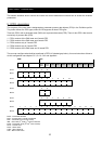
In the request message the first two bytes are used for parameter identification. The first digit (7) denotes the
function “Change parameter value (array word)” (refer to chapter 3.2). The second digit along with the second
byte (3 and 93) indicates parameter number 916. Byte 3 (01) denotes sub-index in the array parameter, in this
case “01” means the first index in the array. Bytes 7 and 8 (00 3D = 61dec) contains the parameter number that
shall be mapped. This means that in the PZD3 place the read value of parameter A038 (Profibus parameter
number 61dec) shall be transferred from the inverter to the master every bus-cycle.
In the response message, the first digit (4) indicates the function “Transfer parameter value (array word)”. Sub-
index (01 00), value (00 3D in bytes 7 and 8) and parameter number (x3 94) are mirrored from the request. In the
PZD3 field (word 7) the value (01 F4 = 500dec, 5.00 Hz) of “Jogging frequency” is transferred.
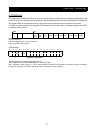
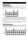
5.4.3 Writing a two byte array parameter #2
In this third example, we are configuring PZD3 to contain the value of parameter A004, “1
st
Maximum frequency”
in the request from the master to the inverter. PPO2 is used. On Profibus parameter A004 corresponds to
parameter number 62 (3Eh). This is configured with parameter number 915 (393h), “Assignment of PZD write
word” (see also chapter 5.3.3 and 5.5).
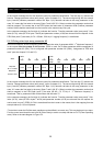
PKW PZD
Word 1
PKE
2
IND
3
PWE
4
PWE
5
STW
ZSW
6
HSW
HIW
7
PZD3
8
PZD4
9
PZD5
10
PZD6
Request:
PLC->Inverter
73 93 01 00 00 00 00 3E 04 7F 20 00 00 4B 00 00 00 00 00 00
Response:
Inverter->PLC
43 93 01 00 00 00 00 3E 03 37 20 00 01 F4 00 00 00 00 00 00
In the request message the first two bytes are used for parameter identification. The first digit (7) denotes the
function “Change parameter value (array word)” (refer to chapter 3.2). The second digit along with the second
byte (3 and 93) indicates parameter number 915. Byte 3 (01) denotes sub-index in the array parameter, in this
case “01” means the first index in the array. Bytes 7 and 8 (00 3E = 62dec) contains the parameter number that
shall be mapped. In the PZD3 field (word 7) the value (00 4B = 75, 75 Hz) of “1
st
Maximum frequency” is
transferred. That is, parameter A004 will be written with the value 75.
In the response message, the first digit (4) indicates the function “Transfer parameter value (array word)”. Sub-
index (01 00), value (00 3E in bytes 7 and 8) and parameter number (x3 93) are mirrored from the request. As
can be seen in word 7 (PZD3) 01 F4h is transferred from the inverter to the master, that is the mapping from the
example above (5.4.2) is still present.
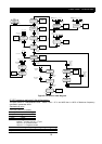
*To start the inverter the Profibus state machine must be shifted in a correct way. This may be done in two steps.
First the control word should be set to 04 06 (Enter
Ready to switch-on state
) and then to 04 7F (Enter Operating
state). Refer to the state diagram in Figure 5-2.