


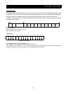
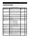
CHAPTER5 OPERATING
15
START
Voltage
switched-off,
SW=0
OFF3 Active
Voltage on
CW: bit 0=0
bit 10=1
Not ready for
switch-on
SW: bit 5=0
SW: bit 0=0
bit 2=0
bit 6=0
CW: bit 0=0
bit 1=1
bit 2=1
bit 10=1
Ready for
switch-on
SW: bit 0=1
bit 4=1
bit 5=1
CW: bit 0=1
bit 10=1
Ready
SW: bit 1=1
Inhibit operation
active
Operation
inhibit
SW: bit 0=1
bit 4=1
bit 5=1
CW: bit 3=0
bit 10=1
A
CBD
Enable operation
CW: bit 3=1
bit 10=1
SW: bit 2=1
CW: bit 4=1
bit 10=1
CW: bit 4=0
CBD
Ready A B C D
CW: bit 0=0
bit 10=1
OFF1 Active
Stage 1
OFF1 Active
Stage 2
SW: bit 1=0
n(f)=0, I=0
Load contactor open
Ready A B C D
Ready to
switch-on
OFF2 Active
SW: bit 4=0
CW: bit 1=0
bit 10=1
Ready A B C D
Ready to
switch-on
CW: bit 2=0
bit 10=1
Fault
Ready A B C D
Ready to
switch-on
Fault
SW: bit 3=1
CW: bit 7=1
A
RFG enabled
output
CD
CW: bit 5=0
bit 10=1
B
CW: bit 5=1
bit 10=1
RFG Acc
enabled
D
CW: bit 6=0
bit 10=1
D
CW: bit 6=1
bit 10=1
Operating status
Outputing
frequency
(bit 10=1)
Switch-on inhibit
SW: bit0=0
bit1=0
bit2=0
bit 6=1
Drive running
Jogging active
Jog setpoint
to speed
controller
CW: bit 8=1
bit4=0
bit5=0
bit6=0
bit 10=1
CW: bit 8=0 or
bit 10=1
Jogging-pause
monitoring
n(f)=0, I=0
CW: bit 8=1
bit4=0
bit5=0
bit6=0
bit 10=1
n(f)=0, I=0
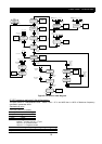
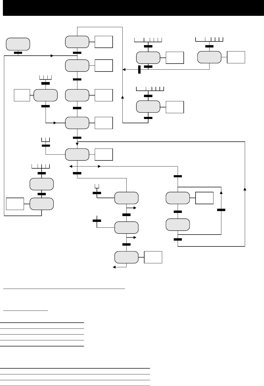
Figure 5-2 Profidrive state diagram
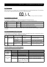
5.3.2 Frequency set-point/ Actual frequency
The data format is “Standardized value”, where 0 hex = 0 % and 4000 hex is 100% of Maximum frequency
specified in parameter A004.
Standardized value
A linear value.
0%=0 (0h), 100% is 2
14
(4000h)
Data type N2
Range -200%…200%-2
-14
Resolution 2
-14
= 0.0061%
Length 2 bytes
Notation: 2’s complement notation.
MSB is 1
st
bit after sign bit in 1
st
byte.
Sign bit = 0 = positive number
Sign bit = 1 = negative number
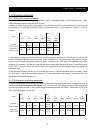
Bit 8 7 6 5 4 3 2 1
Byte 1 SIGN 2
0
2
-1
2
-2
2
-3
2
-4
2
-5
2
-6
Byte 2 2
-7
2
-8
2
-9
2
-10
2
-11
2
-12
2
-13
2
-14